Chapter 5 – Parameter List
4-8
4.3.8 Saving and Resetting Parameters
Parameter Name Code Description (Default Value)
Para. Read FG2-91 Reads parameters from VFD and saves to a keypad memory (No)
Para. Write FG2-92 Writes parameters from keypad memory to VFD memory (No)
Para. Init. FG2-93 Initializes either all program groups or selected one (No)
Para. Save FG2-95 Saves parameters permanently to VFD memory (No)
Note: All these parameters work only in VFD stop mode. It is recommended to save current parameters to a keypad
before initializing VFD during trouble-shooting. This way the VFD can be returned to current state at any point.
4.3.9 Auto start parameters
Parameters for VFD auto start in different conditions
Parameter Name Code Description (Default Value)
Power On Run FG2-19 VFD auto starts after power up with present run command (Yes)
RST Restart FG2-21 VFD auto starts after fault reset with present run command (Yes)
IPF Mode FG2-22 VFD auto starts after Instantaneous Power Failure (Yes)
4.3.10 Control Methods and Patterns
Parameter Name Code Description (Default Value)
Stop Mode SET-16 Four Stop Modes: Decel, DC-Brake, Cost, Flux Brake (Decel)
PID Mode SET-20 Proportional-Integral control mode (No)
MMC Mode SET-50 Starts Auxiliary Motors at High Demand (No)
Acc. Pattern FG1-01 Acceleration curves: Linear, S-curve, U-curve (Linear)
Dec. Pattern FG1-02 Deceleration curves: Linear, S-curve, U-curve (Linear)
PreHeat Mode FG1-10 Provides Motor Winding Preheat in VFD stop mode (No)
Start Mode FG1-20 Three Start Modes: Accel, DC-Start, Flying Start (Accel)
Safety Stop FG1-28 During Power loss VFD decelerates using load inertia (No)
V/F Pattern FG1-40 Three Patterns: Linear, Square, User V/F (Linear)
Energy Save FG1-51
Decreases output voltage at steady speed to save energy. (None)
Control Mode FG2-60 Three modes: V/F, Sleep Compensation, Sensorless (V/F)
Torque Boost FG2-67 Provides initial voltage at start for torque boost (Manual)
4.4 Control Wiring Configurations
4.4.1 Examples of digital control configurations
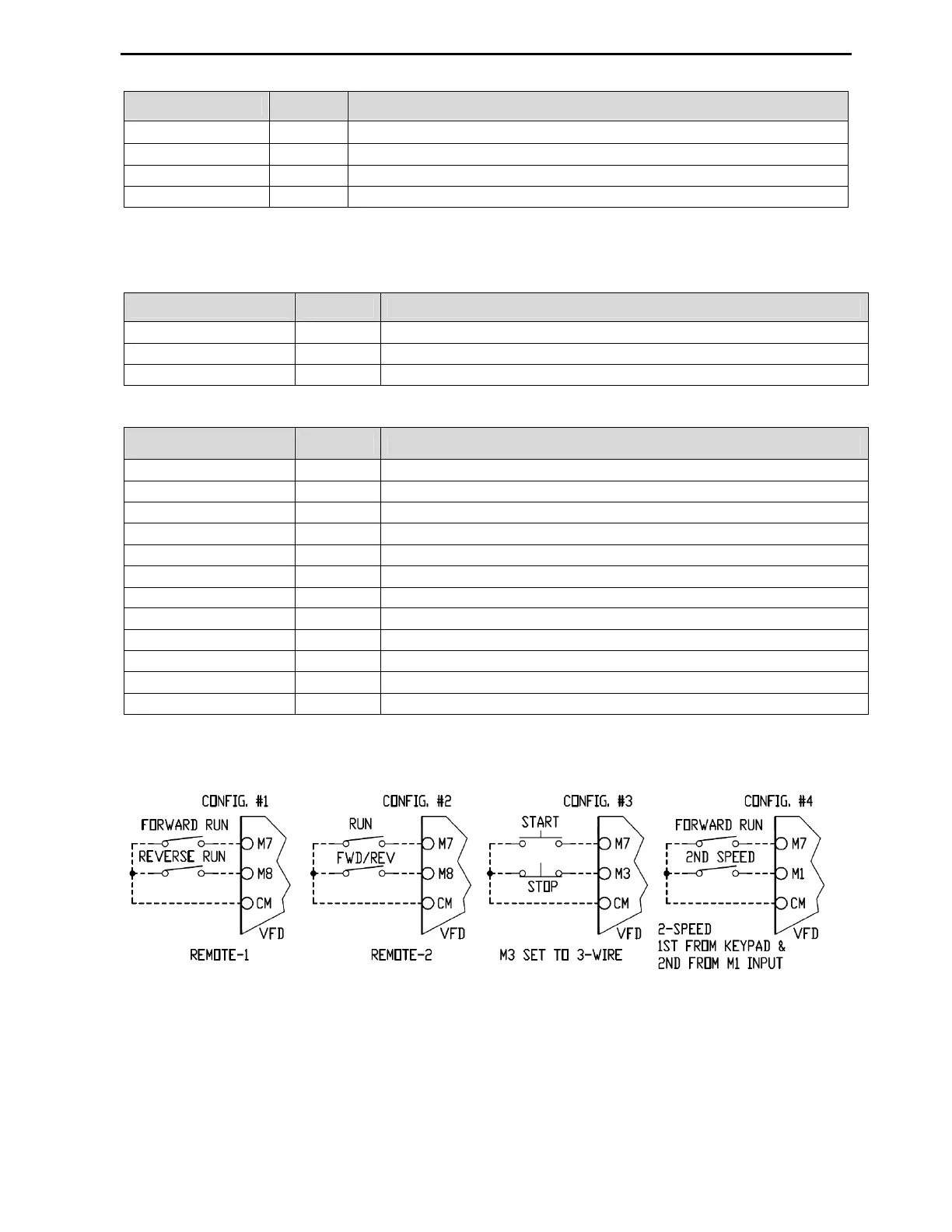
The 4.4.1 picture shows four most common control configurations.
Config. #1 shows VFD controlled by separate Forward and Reverse inputs when SET-09 parameter is set to
Remote-1 mode. If both inputs are activated simultaneously, the VFD will stop.
Config. #2 shows VFD controlled by Run and Forward/Reverse inputs when SET-09 parameter is set to
Remote-2 mode. Forward Run mode is activated by Run input and Reverse mode by both Run and Fwd/Rev
inputs.
Config. #3 shows VFD controlled by Start/Stop momentary push buttons when SET-09 parameter is set to
Remote-1 mode and M3 input to 3-Wire. When Start button is pressed, the VFD starts Forward. The VFD
stops when Stop button is pressed.
Config. #4 shows 2-Speed VFD control. Parameter SET-09 is set to Remote-1 mode and SET-10 to