Chapter 9 - Options
9-1
CHAPTER 9 - OPTIONS
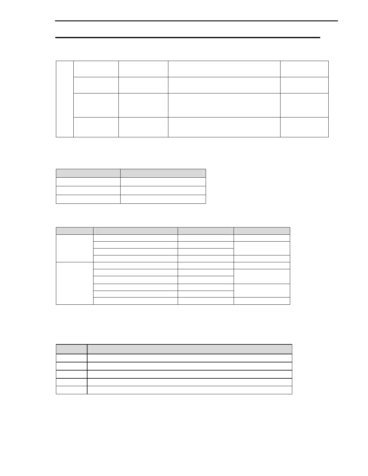
9.1 Option List
External
Keypad LCD 32 character display
keypad Download and Upload available
All units
Remote Remote cable 6, 9 and 15-foot long keypad cable to
control VFD from remote keypad.
Optional
Dynamic
braking
DB unit and
resistor
Allows VFD to decelerate rapidly without
overvoltage fault.
Optional
Conduit box
option
NEMA TYPE 1
Conduit box
Install it for NEMA TYPE 1 rating. 20~125HP
15~90kW
Note: Refer to Option manual for details.
9.2 Remote Keypad Cable
Ordering No.
Description
CI-RKPK-EXT2M-P/S
Remote cable –6ft
CI-RKPK-EXT3M-P/S
Remote cable – 9ft
CI-RKPK-EXT5M-P/S
Remote cable – 15ft
9.3 DBU (Dynamic Braking Unit) sizes
230V class
Frame 2
480V class
Frame 2
40 ~ 50 HP (30 ~ 37 kW) CI-DBU-40-4
Frame 3
Note: P Series VFD does not have internal dynamic braking transistor and DB resistor and requires
external DBU and DBR set. Refer to DBU manual for multiple units and resistors arrangement.
9.4 DBU and DBR terminals and wiring
Terminals
Description
Connect to system Ground terminal
Connect to DB Resistor’s
Connect to DB Resistor’s
Connect to VFD Positive terminal
Note: Refer to DBU and DBR manuals for proper wiring instructions.