Chapter 3 – Installation & Wiring
3-9
3.3 Control Circuits Wiring
3.3.1 Wiring Recommendations
The CM and 5G terminals are isolated from each other and from the ground. Do not connect these
terminals to the ground, otherwise it can cause some electrical noise in control circuits and unstable VFD
operation or malfunction.
Use shielded cable or twisted wires for 24VDC digital control circuits wiring and separate these wires
from the main power and motor wiring and other high voltage circuits.
Use shielded cable for analog control circuits with shield connected to the ground.
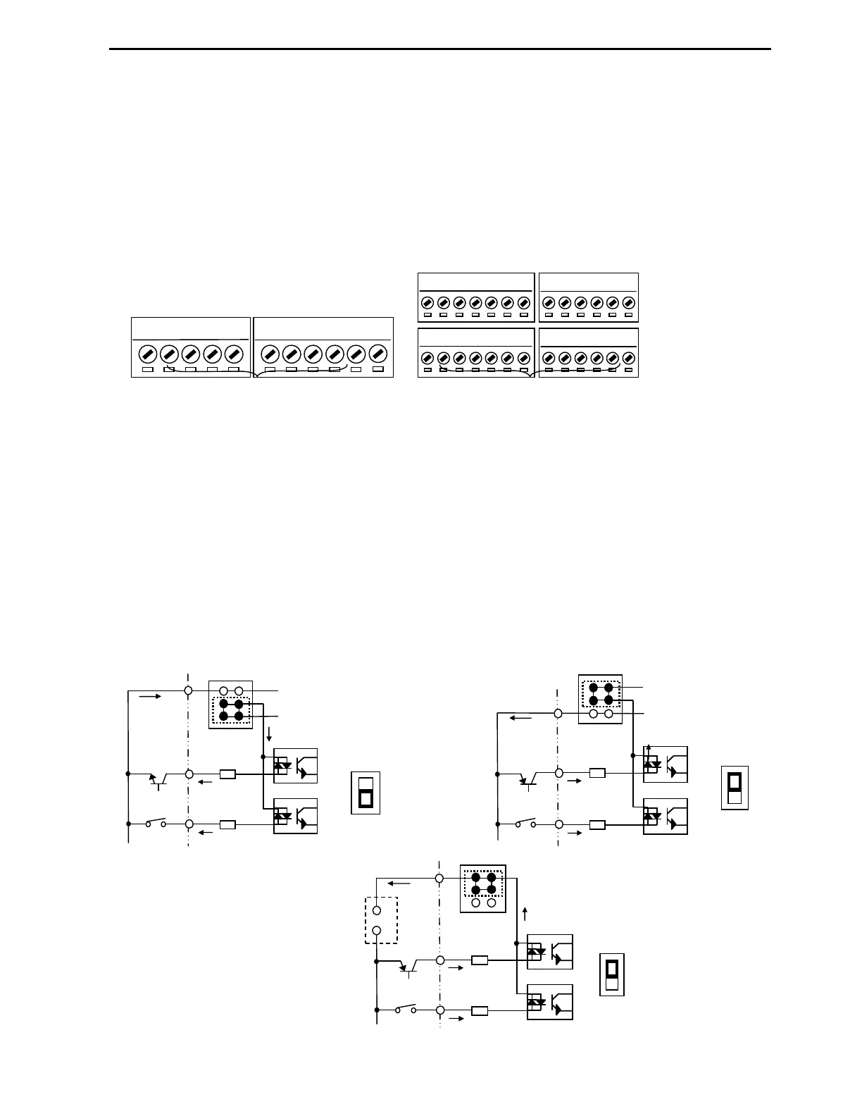
3.3.2 Control terminals layout and recommended wire gauge.
3.3.3 NPN and PNP 24VDC Digital Control Modes
P Series provides Sink or Source (NPN or PNP) modes for digital control inputs.
The digital inputs configurations are selectable by J1 switch between Sink mode (NPN) and Source mode
(PNP).
• Sink (NPN) mode. Put J1 switch down to NPN position. CM terminal (-24VAC) is common terminal
for digital inputs. The factory default is Sink mode (NPN).
• Source (PNP) mode with internal power supply. Put J1 switch up to PNP position. Terminal 24
(+24VDC) is common terminal for digital inputs.
• Source (PNP) mode with external power supply. Put J1 switch up to set to PNP position. The external
24VDC Power Supply negative terminal should be connected to VFD CM terminal and positive terminal
will be common for all digital inputs.
•
A0
B0
5G
5G
S0
S1
V+
V1
5G
V-
I
NT
C+
CM
C-
M6
24
M7
M8
M1
CM
M2
M3
24
M4
M5
3A
3C
3B
A1
C1
A2
C2
A3
C3
A4
C4
Relay outputs
Digital and analog control
22 AWG (0.33mm
2
) ~ 14 AWG (2.0mm
2
)
28 AWG (0.08mm
2
) ~16 AWG (1.25mm
2
)
Sink mode (NPN)
Source mode (PNP) with external
24VDC Power source
Source mode (PNP)
J1
-
--
-
+
++
+
Internal 24VDC
Power Supply
(-24V)
CM
M8(RX)
J1
PNP
J1
External 24VDC
Power Supply
(-24V)
CM
M8(RX)
-
--
-
+
++
+
J1
NPN
-
--
-
+
++
+
J1
Internal 24VDC
Power Supply
(+24V)
24
M7(FX)
M8(RX)
J1
NPN
PNP