Chapter 8 - Troubleshooting & Maintenance
8-4
Check diodes in the rectifier bridge and IGBT module with multimeter in the sequence shown in
below table and diagram. Diode state codes: C- Closed and O- Open.
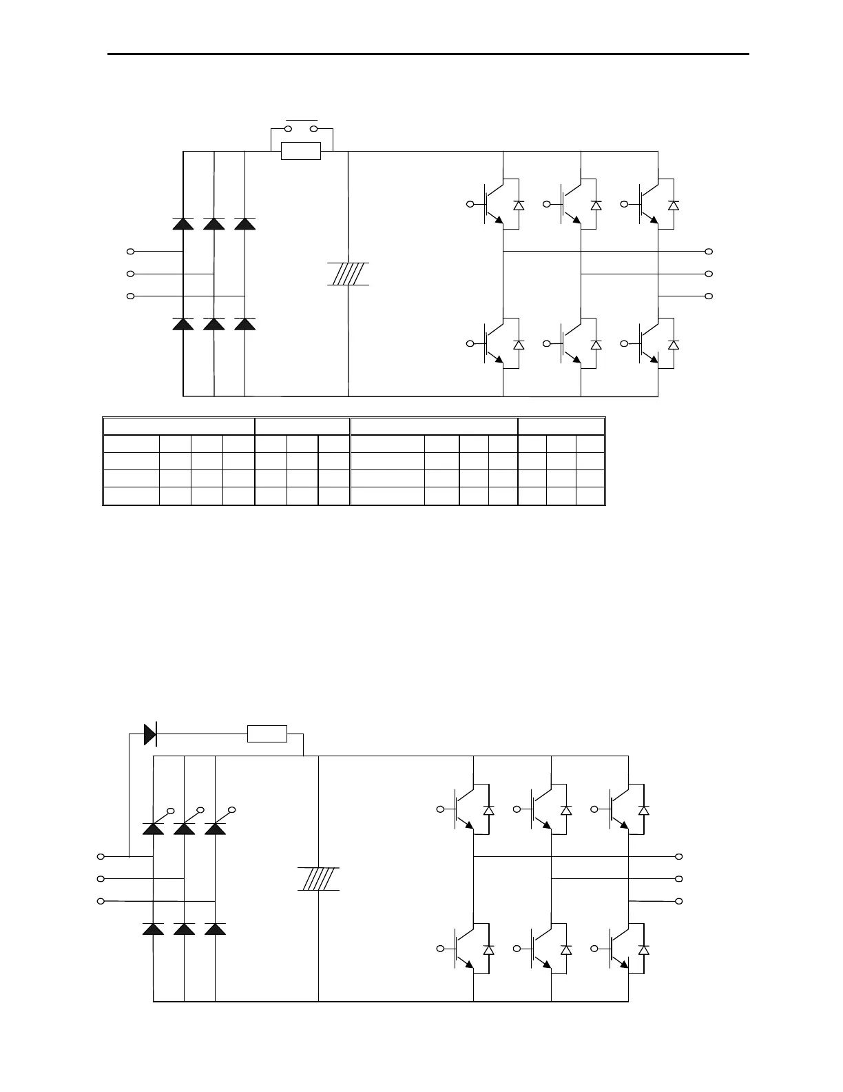
8.4.2 Diode Bridge and IGBT Module Test for 50~700HP VFDs
Before checking the power components, disconnect AC input power and wait for about 10 minutes.
Check that there is no DC voltage on P1+ and N- terminals.
Disconnect power wires from R, S, and T terminals and motor leads from U, V, and W terminals.
Check diodes in the rectifier bridge and IGBT module with multimeter in the sequence shown in
below table and diagram. Diode state codes: C- Closed and O- Open.
Note: The 50-700HP VFDs have half controlled rectifier bridge with SCRs (silicon controlled rectifier).
The SCR cannot be checked for open state with multimeter. The reading from R to P1 terminals will
represent charge diode and resistor circuit. Terminals S and T to P1 will show closed state in direct and
reverse test if SCRs are not shorted.
Lead to
to
to
to
to
R S T R S T
to
R S T R S T
State
State
to
to
State
State
Charge
Resistor
M/C Contact
+
++
+
DC Bus
Capacitors
DC Bus Positive
(P1+)
(N-) DC Bus Negative
IGBT transistors
Six- Pulse
Rectifier Bridge
Charge Diode and Resistor
SCRs
DIODES
+
++
+
Capacitors
DC Bus Positive
(P1+)
(N-) DC Bus Negative
IGBT transistors