Chapter 6 - Parameter Description
6-25
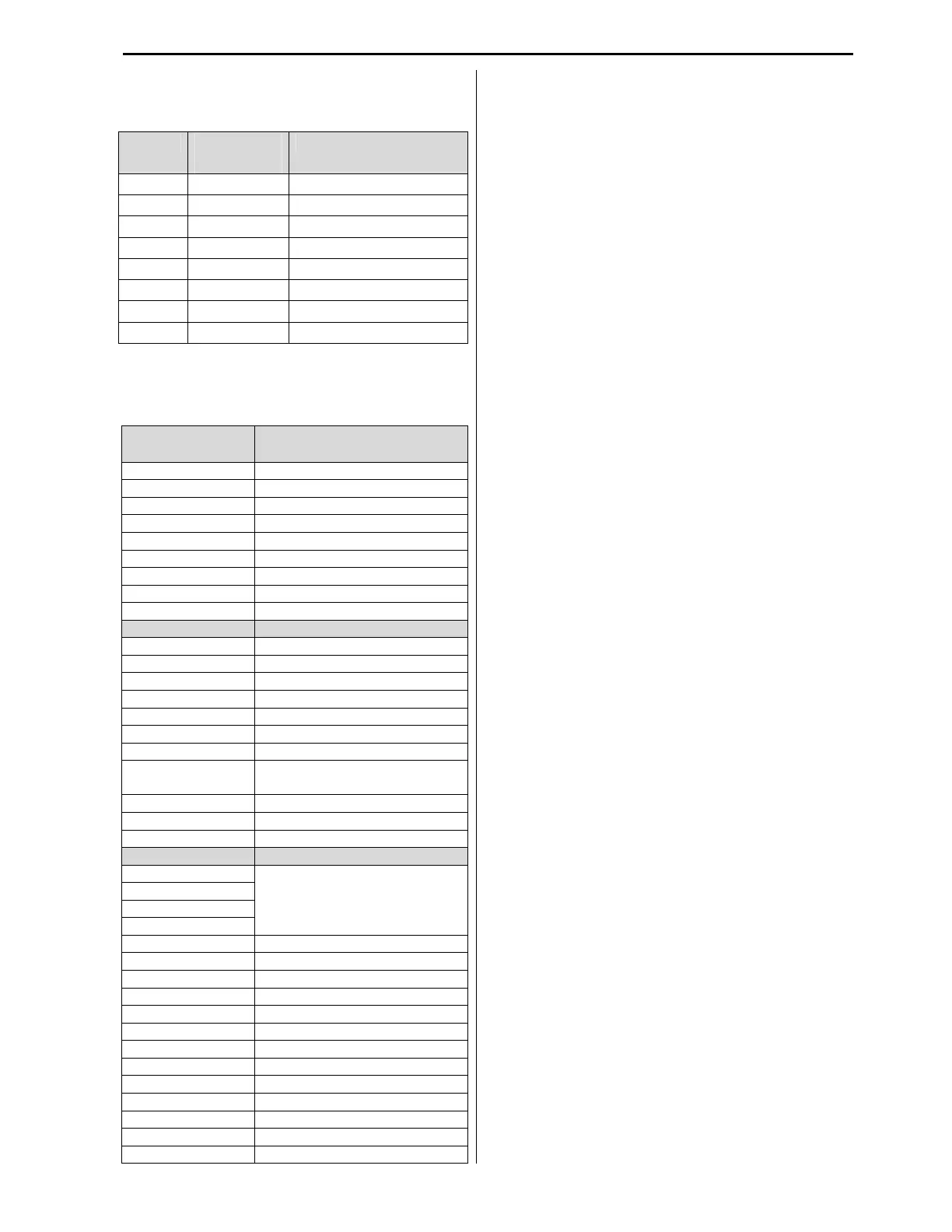
any available selection. The table below shows the
default settings for all eight inputs.
Code LCD
Default
I/O-20 M1 define SPEED-L (Low)
I/O-21 M2 define SPEED-M (Middle)
I/O-22 M3 define SPEED-H (High)
I/O-23 M4 define Reset
I/O-24 M5 define BX (Emergency Stop)
I/O-25 M6 define JOG
I/O-26 M7 define FX (Forward Run)
I/O-27 M8 define RX (Reverse Run)
Note: Programming mode is disabled when BX
input is active.
Selection of M1~ M8 in I/O-20~27
Setting Range Description
Speed-L Multi-step speed - Low
Speed-M Multi-step speed - Middle
Speed-H Multi-step speed - High
XCEL-L Multi-accel/decel - Low
XCEL-M Multi-accel/decel - Middle
XCEL-H Multi-accel/decel - High
Dc-brake DC injection braking during stop
2nd
Func Switch to 2
functions
Exchange Switch to bypass contactor
-Reserved- Reserved for future use
Up Increase Speed
Down Decrease Speed
3-Wire Start/Stop Pushbutton operation
Ext Trip External trip
Pre-heat Motor Winding Pre-heat function
iTerm Clear Clears accumulated error for PID
Open-loop Switches from PID to V/F mode
Loc/Rem
Switches from Remote to Local
control
Analog hold Holds analog input signal value
XCEL stop Disable Accel and Decel modes
P Gain2 Switches to 2
P-Gain for PID
-Reserved- Reserved for future use
Interlock1
Used for MMC operation
Interlock2
Interlock3
Interlock4
Speed-X Additional Step Frequency
Reset Resets VFD by digital input
BX BX (Emergency stop)
JOG Enables Jog run at Jog Frequency
FX Forward Run
RX Reverse Run
ANA Change Switches from V1 to I input
Ext.PID Run External PID Run/Stop
Up/Dwn Clr Clears Up/Dwn Control Speed
Jog_FX Jog Forward
Jog_RX Jog Reverse
Damper SW Damper Switch Input
Smoke Purge Smoke Purge at High Speed Limit
Speed-L, M, H and X- VFD can run at different
preset speeds based on digital inputs combinations
shown in table for DRV-01~15.
XCEL-L, M and H- If M1, M2 and M3 inputs are
set to XCEL-L, XCEL-M and XCEL-H
respectively, up to 8 different Accel and Decel time
settings can be used.
DC-Brake- DC Injection Braking can be activated
during inverter deceleration by configuring to DC-
Brake and activating one of the Programmable
digital inputs (M1-M8). The DC-Brake function is
described in FG1-15.
2nd Function- The 2nd function can be activated
during inverter stop mode by activating digital
input M1~M8 set to 2
nd
Function. See APP 20~29
for details.
EXCHANGE- When any digital input is set to
Exchange and activated, the VFD stops, deactivates
VFD output contactor and activates Bypass
contactor by pre-programmed AUX relay outputs.
Up, Down- By using the Up and Down function,
the VFD speed will be increased by pressing UP
button and decreased by DOWN button.
3-Wire- This function provides VFD control by
start/stop momentary push buttons. When any
digital input is set to 3-Wire, this control mode is
enabled.
Ext Trip- This N.C. (normally closed) contact
input provides protection for the system by tripping
VFD. When this input is wired to a thermostat of
the Dynamic Braking unit or resistor, VFD will trip
if thermostat contact opens under overheat
condition. The input configuration can be changed
from N.C. to N.O. in parameter I/O-95.
iTerm Clear- This function is used for PID control
to clear an accumulated process error based on I-
Time setting.
Open-loop- This input will switch VFD control
from PID to regular V/F based on SET-10
selection.
Note: The switching works only in VFD stop mode.
LOC/REM- When communication board or
embedded RS485 communication is used for the
speed and run command, the VFD control can be
switched to Local by activating this Loc/Rem input.
Analog hold- When this input is activated, VFD
will “freeze” an analog speed reference signal and
run steady at this speed.
XCEL stop- The VFD stops accelerating and
decelerating when this input is activated.
P-Gain 2- This input can change P-Gain during
PID operation to second value.