Chapter 6 - Parameter Description
6-32
The VFD display will show LOR fault at com. loss.
I/O-94 setting is for communication using RS232-
RS485 converter and should be set according to
converter specification. This time setting creates a
delay before VFD sends response.
$)57+"!""1
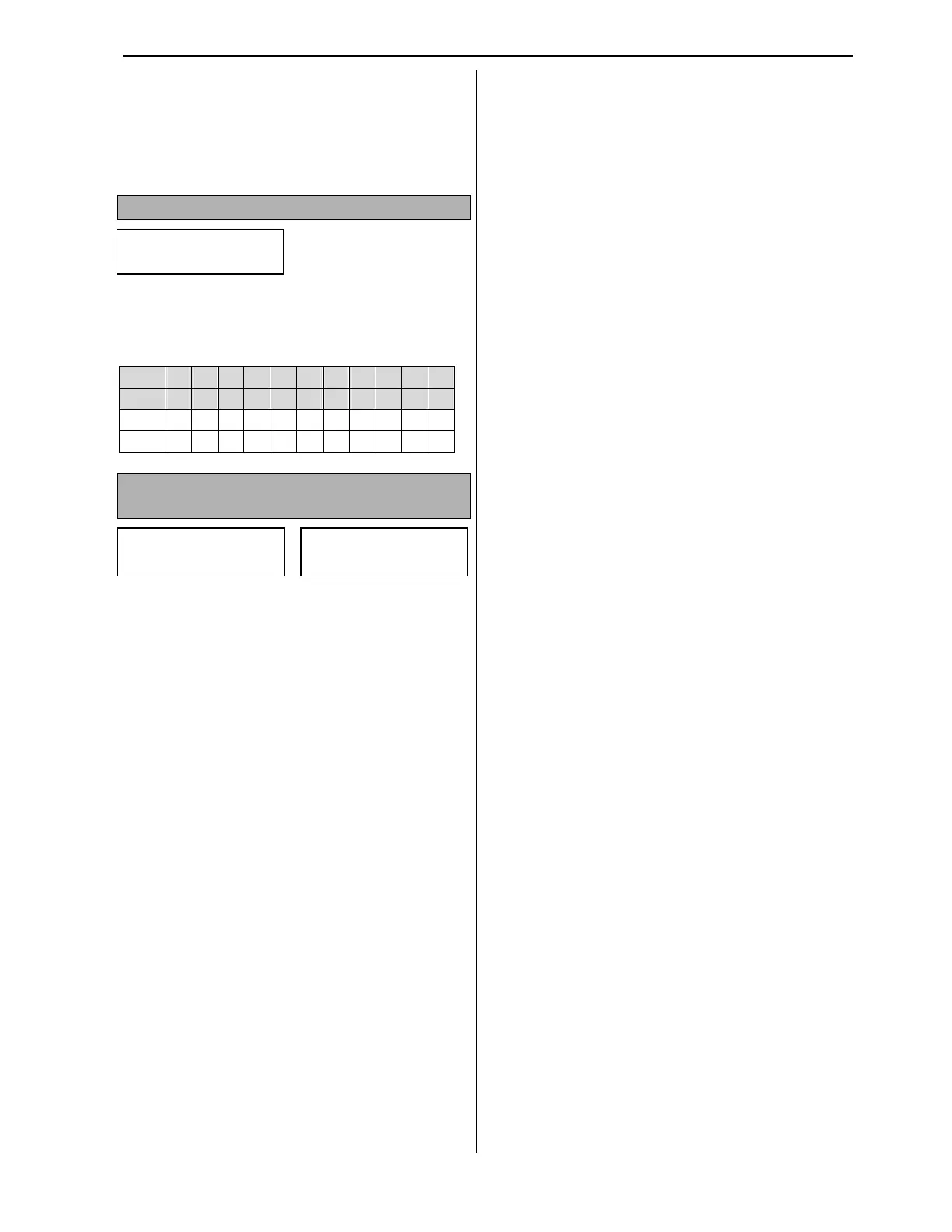
The digital input N.O. type can be changed to N.C.
in I/O-95 by setting a corresponding bit to 1. The
below table shows the digital inputs bit mapping.
Input P6
P5
P4
M8
M7
M6
M5
M4
M3
M2
M1
bit 10
9 8 7 6 5 4 3 2 1 0
N.O.
0 0 0 0 0 0 0 0 0 0 0
N.C. 1 1 1 1 1 1 1 1 1 1 1
$)53654+ "&", " !!
" '"
The VFD can monitor motor temperature with
thermistor PTC (positive temperature coefficient)
or NTC (negative temperature coefficient) sensor
connected to NT or NE and 5G terminal.
I/O-97 has three bits for motor overheat protection
selection. Second bit is not active and reserved for
future use. There are following possible
combinations for this parameter:
010, 000 or 110- The Motor Overheat protection is
disabled.
011 or 001- The Motor Overheat protection is
enabled with PTC thermistor sensor.
111 or 101- The Motor Overheat protection is
enabled with NTC thermistor sensor.
The thermistor rating ±5% at 25°C is for PTC 1k
and for NTC 2.545k. The temperature range is for
PTC 0-125°C and for NTC 0-150°C.
I/O-98 is the motor overheat temperature setting in
Celsius. The VFD will trip when motor temperature
exceeds the I/O-98 value.
I/O
In No/NC Set
95 00000000000
I/O OH Trip Sel
97 010
I/O MO Trip Temp
98 110°C