EasyManua.ls Logo

Chore-Time Chore-Tronics 3 Control - User Manual

Chore-Time Chore-Tronics 3 Control
142 pages
Print Icon
To Next Page IconTo Next Page
Loading...
Chore-Tronics
®
3 Control
Installation & Operators Instruction Manual
MT2398CNovember 2013

Table of Contents

Questions and Answers

  • K
    Katherine ZunigaAug 27, 2025
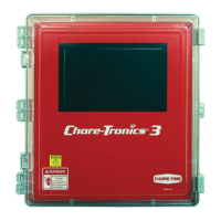
    How to fix Chore-Time Home Automation display that is difficult to read?
    • L
      lgriffinAug 27, 2025
      If the display is difficult to read, it might be because the back light on the display board is unplugged or defective. Check the two-wire plug on the display board and replace it if defective.
  • J
    Julie TorresAug 27, 2025
    What to do if Chore-Time Chore-Tronics 3 Control Home Automation tunnel curtain opens in Power Mode?
    • C
      ctaylorAug 27, 2025
      If the tunnel curtain opens in Power Mode, it could be due to: * Normal operation during a Power-Tunnel Mode Transition. * The high static pressure alarm safety feature has taken over. Static pressure had quickly built to above 0.20” and stayed there for over the wind delay setting. The tunnel curtain will open to maintain a static pressure of between 0.18 and 0.20”. This is usually accompanied by a high static pressure alarm. Find the cause of high static pressure and correct it. * Normal operation of the additional inlet area through the Tunnel Curtain feature. Whenever the air inlets do not provide enough air, the tunnel curtain will also open enough to maintain static pressure within the Power Mode limits.
  • P
    Peggy MorrisAug 25, 2025
    Why Chore-Time Chore-Tronics 3 Control Home Automation fan assigned to Power Mode is running in Natural Mode?
    • G
      gomezvanessaAug 26, 2025
      If a fan assigned to operate in Power Mode only is running in Natural Mode, it could be due to: * A “Pot Not Responding” or a “Pot Outside Limits” alarm has occurred. Find out the cause of the alarm and correct it. Please see Potentiometer troubleshooting section for suggestions. * The fan switch is in the "Manual ON" position. Move the switch to automatic.
  • R
    Russell OrrAug 25, 2025
    What to do if Chore-Time Chore-Tronics 3 Control Home Automation temperature readings are not steady?
    • K
      kristinewhiteAug 25, 2025
      Unsteady temperature readings in your Chore-Time Home Automation system, where the temperature changes by half a degree or more every five seconds, can cause tunnel fans and heaters to run simultaneously. This issue is often due to excessive noise on the temperature sensors. To resolve this: * Use non-shielded Twisted Pair Wire (part no. 42208) for the temperature sensor. * Run the wire separately from high voltage wires. * Ensure the wire enters the control in a separate place from the high voltage wire, if possible. * Avoid using Romex, SJO cord, or shielded wire as temperature sensor wire.

Summary

Chore-Time Warranty

Conditions and Limitations

Outlines the conditions and limitations applicable to the Chore-Time warranty, including voiding conditions and exclusions.

General Information

Support and Safety Information

Provides support information, emphasizes safety warnings, and describes safety decals for equipment operation.

Introduction to the Control

Display Screen and Navigation

Explains the touch screen display, navigation methods (touch/mouse), and screen layout elements.

Keypad and Control Interface

Details the numeric keypad and keyboard functions for data entry and control interaction.

Graphs and Relay Box Indicators

Describes graph displays and the function of relay box indication lights and auto/manual switches.

Glossary of Terms

Overview of Screens

Alarms Overview

Explains how to view active and recovered alarms, including alarm status and notice functions.

Control Setup

General and Unit Settings

Covers general setup, language, time/date configuration, and unit of measurement selection.

Analog Input Configuration

Details the setup and calibration of various analog inputs including temperature, static pressure, and humidity sensors.

Digital Input Configuration

Explains how to configure digital inputs such as water meters, feed scales, and airspeed sensors.

House and Output Assignments

Covers house setup, mortality tracking, and assigning equipment to control outputs.

Ventilation Modes and Settings

Details configuration for ventilation modes like Tunnel, Stir, Exhaust, Cool, Cool Pad, and Heat Zones.

Clock and Miscellaneous Outputs

Covers clock assignments for lights, feed, spares, and miscellaneous output configurations like backup relays.

Curve and Temperature Settings

Explains setup for ventilation settings, static pressure, curves, and temperature influences.

Management and Program Setup

Covers mortality tracking, flock setup, and program/setup key management for control configurations.

Control Operation Overview

Standard Mode Functionality

Describes Power and Natural mode functionalities, including curtain movement timing and rate.

Control Installation

Mounting and Wiring Basics

Provides guidelines for mounting the control boxes and basic wiring principles, including wire routing.

Input Wiring Procedures

Details wiring for analog inputs (temperature, static pressure, humidity) and digital inputs (meters, switches).

Expansion Board and Scale Wiring

Covers wiring for bird scales, expansion boards, and related components.

Output and System Testing

Explains manual testing of outputs, back-up box testing, and relay assignments.

PC Connection

Troubleshooting

Programming and Configuration Issues

Addresses common problems related to programming, fan operation, and temperature set points.

Equipment and Potentiometer Problems

Details troubleshooting steps for display issues, pressure readings, and potentiometer response.

Network and System Errors

Provides solutions for IONet communication failures and other system-level errors.

Wiring Diagrams

Backup Control and Fan Wiring

Illustrates wiring diagrams for backup control systems and typical fan connections.

Specialized Equipment Wiring

Shows wiring diagrams for linear lifts, turbo-cool systems, I/O boards, and brooders.

Improving Lightning Surge Suppression

Surge Protection System Installation

Details the installation of farm and house main service panel surge suppressors for lightning protection.

Telephone Line Surge Suppression

Explains the wiring and installation of surge suppressors for FNET/ALARM and telephone lines.

Parts Information

Main Box Parts Listing

Lists itemized parts and their corresponding part numbers for the main control box.

Relay Box Parts Listing

Provides a list of itemized parts and their part numbers specifically for the relay box.

Extra Parts and Kits

Lists optional add-on kits and repair boards for expanding system functionality.

Input Wiring Assignment Diagram

Technical Specifications

Revisions to this Manual

Details the changes and revisions made to the manual, including page numbers and descriptions.

Chore-Time Chore-Tronics 3 Control Specifications

General IconGeneral
BrandChore-Time
ModelChore-Tronics 3 Control
CategoryHome Automation
LanguageEnglish