POWER BRAKES
GENERAL INFORMATION
The purpose of the vacuum operated power brake
booster. Is to reduce the amount of force applied to the
brake pedal by the drivers foot. To obtain the required
hydraulic pressure in the brake system to stop the
vehicle.
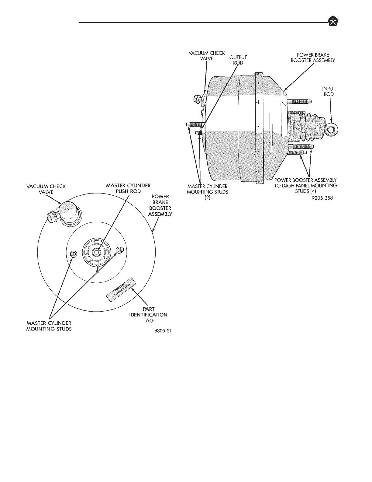
The power brake booster can be identified if required,
by the tag attached to the body of the booster assembly
(Fig. 1). This tag contains the following information.
The production part number of the power booster
assembly, the date it was built and who manufactured
it.
The power brake booster assembly is not a
repairable part and must be replaced as a com-
plete unit if it is found to be faulty in any way.
The power booster vacuum check valve is not
repairable but can be replaced as an assembly.
The power brake booster in vacuum operated. The
vacuum is supplied from the intake manifold on the
engine through the power brake booster check valve
(Fig. 1).
As the brake pedal is depressed, the power boosters
input rod moves forward. This opens and closes valves
in the power booster, creating a vacuum on one side of
a diaphragm and allowing atmospheric pressure to
enter on the other. This difference in pressure forces
the output rod of the power booster out against the
primary piston of the master cylinder. As the pistons in
the master cylinder move forward this creates the
hydraulic pressure in the brake system.
Different systems and engine combinations require
different vacuum hose routings.
The power brake booster assembly mounts on the
engine side of the dash panel. It is externally con-
nected to the brake system by an input push rod to
the brake pedal. A vacuum line connects the power
booster to the intake manifold. The master cylinder
is bolted to the front of the power brake booster as-
sembly.
SERVICE PROCEDURES
POWER BRAKE BOOSTER ASSEMBLY
REMOVE
(1) Remove both wiper arm assemblies.
(2) Remove cowl panel cover from cowl to expose
windshield wiper module.
(3) Remove the 5 screws attaching the windshield
wiper module to the dash panel. Remove the wind-
shield wiper module from dash panel.
(4) Remove the 2 nuts (Fig. 3) attaching master
cylinder assembly to power brake unit.
(5) Carefully slide master cylinder off mounting
studs with brake lines attached, and allow the as-
sembly to rest against left shock tower.
(6) Disconnect vacuum hose from power brake
booster check valve (Fig. 1). DO NOT REMOVE
CHECK VALVE FROM POWER BRAKE
BOOSTER.
Fig. 2 Power Brake Booster Assembly
Fig. 1 Power Brake Booster Identification
5 - 72 BRAKES