DOOR LOCK SYSTEM TEST
For complete testing of the automatic door lock sys-
tems, refer to the 1993 LH Body Diagnostic Proce-
dures Manual.
WIRING VOLTAGE TEST
The following wiring test sequence determines
whether or not voltage is continuous through the
body harness to switch.
(1) Remove left side switch from door trim panel.
(2) Carefully separate multiple terminal block on
wiring harness from switch body.
(3) Connect one lead of test light to a ground ter-
minal:
• Black Wire
• Touch other test light lead to Red Wire terminal.
• If test light comes on, the wiring circuit between
the battery and switch is functional.
• If test light does not come on, check 30 amp circuit
breaker or for a open circuit.
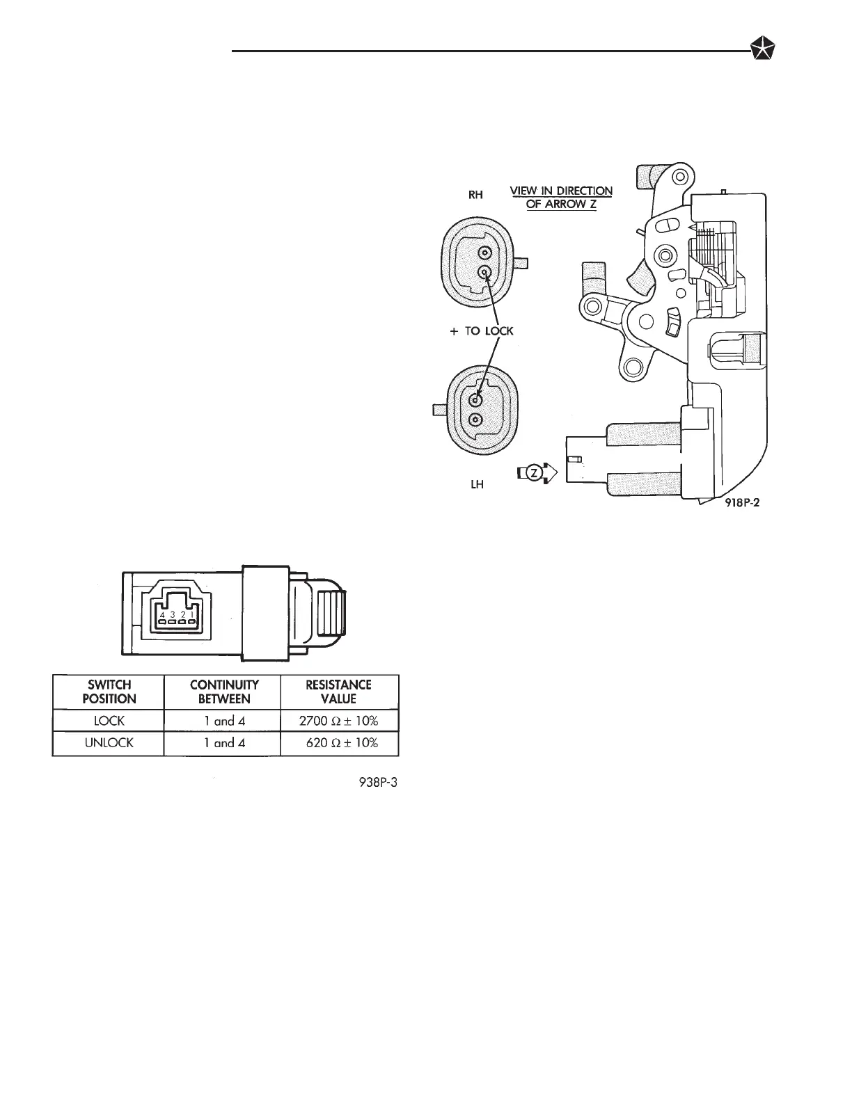
SWITCH TEST
Remove the switch from its mounting location. Us-
ing an ohmmeter, refer to Fig. 1 to determine if con-
tinuity is correct in the Lock and Unlock switch
positions. If these results are not obtained, replace
the switch.
ELECTRIC MOTOR TEST
Make certain battery is in normal condition before
circuits are tested.
To determine which motor is faulty, check each in-
dividual door for electrical lock and unlock or discon-
nect the motor connectors one at a time, while
operating the door lock switch. In the event that
none of the motors work, the problem maybe caused
by a shorted motor, or a bad switch. Disconnecting
the defective motor will allow the others to work.
To test an individual door lock motor, disconnect
the electrical connector from the motor. To lock the
door, connect a 12 volt power source to the positive
pin of the lock motor and a ground wire to the other
pin (Fig. 2). To unlock the door reverse the wire con-
nections at the motor pin terminals. If these results
are NOT obtained, replace the motor.
DOOR LOCK SYSTEM TEST
For complete testing of the body automatic door
lock systems, refer to the 1993 LH Body Diagnostics
Manual.
DOOR LOCK MOTOR REPLACEMENT
(1) Remove door trim panel, refer to Group 23,
Body for removal procedures.
(2) Disconnect motor linkage at the latch/lock mo-
tor (Fig. 2).
(3) Disconnect motor wire connector.
(4) Remove latch/lock assembly attaching screws
and remove assembly.
DECK LID OPERATION
For vehicles equipped with electric deck lid release.
TEST
(1) Confirm solenoid lead wire is connected and 10
volts or more are available at solenoid.
(2) Provide proper ground through latch mounting
screws.
(3) Remove latch and examine plunger. Plunger
should spring back when pressed.
(4) Insure that solenoid plunger travel is adequate
approximately 16 mm (5/8 inch).
ADJUSTMENT
Adjust deck lid latch and striker so that deck lid
latches with a moderate slam. With ignition switch
Fig. 1 Door Lock Switch Continuity Test
Fig. 2 Door Lock Motor
8P - 2 POWER LOCKS