WARNING: NEVER DISASSEMBLE THE PASSEN-
GER AIR BAG MODULE, THERE ARE NO SERVICE-
ABLE PARTS WITHIN THE MODULE.
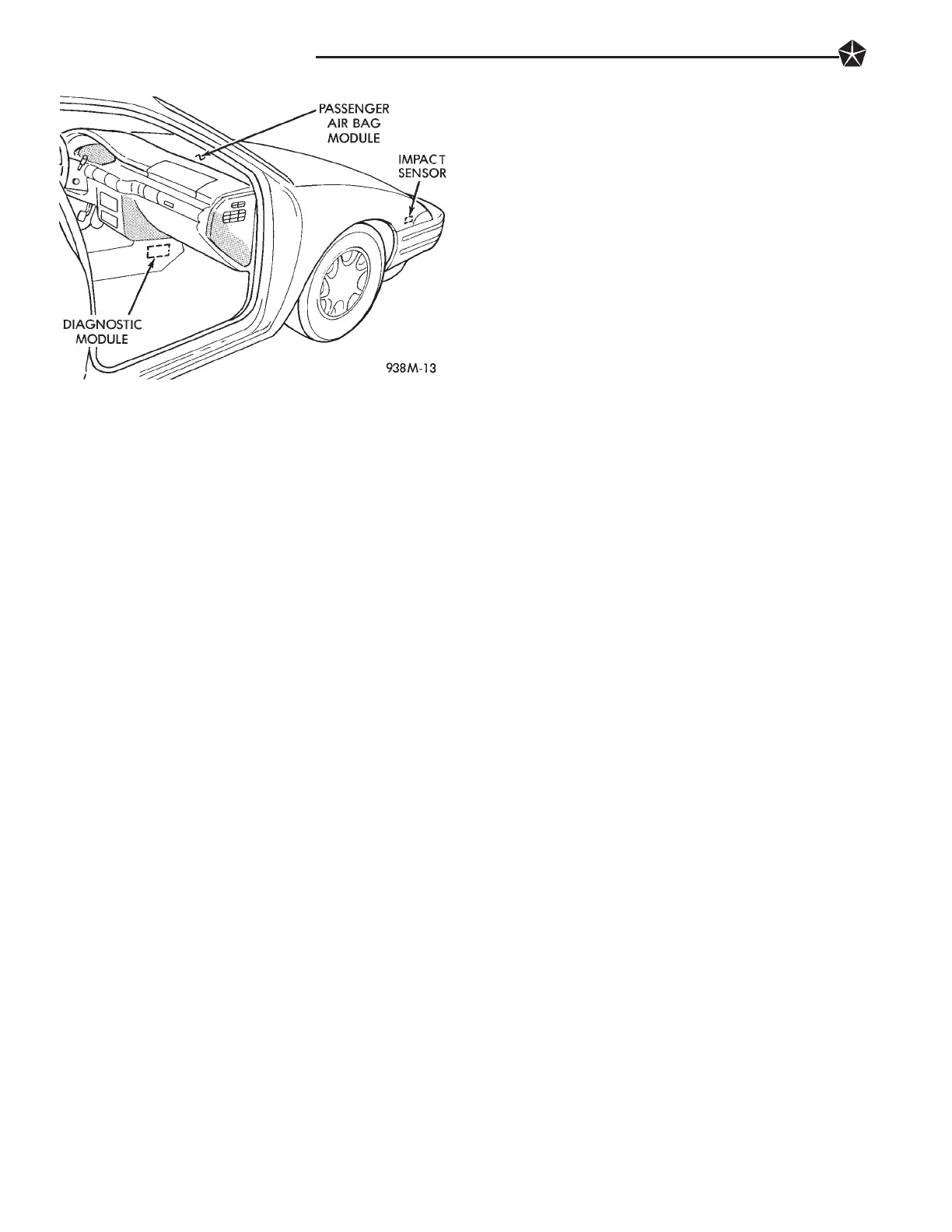
The passenger inflator assembly is within the mod-
ule housing. The module is mounted to the instru-
ment panel retainer, knee bolster and glove box.
When supplied with the proper electrical signal the
inflator will produce a gas and discharge it directly
into the cushion. A protective cover is fitted into the
instrument panel over the air bag module and forms
a decorative cover.
FRONT IMPACT SENSORS
The Driver/Passenger Air Bag System is a supple-
mental safety device designed to help protect the
driver/passenger from serious injury, caused by a
frontal impact of the vehicle.
The two front impact sensors provide verification of
the direction and severity of the impact. The sensors
are mounted on the headlamp carrier surface on the
left and right side of the vehicle under the hood.
The impact sensors are threshold sensitive switches
that complete an electrical circuit when an impact
provides a sufficient acceleration to close the switch.
The sensors are calibrated for the specific vehicle and
react to the severity and direction of the impact.
CLOCKSPRING
The clockspring is mounted to the steering column
behind the steering wheel. The clockspring is used to
maintain a continuous electrical circuit between the
wiring harness and the:
• Driver’s air bag module
• Speed control switches
• Horn switches
The clockspring consists of a flat, ribbon-like, elec-
trically conductive tape which winds and unwinds
with the steering wheel rotation.
DIAGNOSTIC MODULE
The Passenger and Driver Air Bag System Diag-
nostic Module (PASDM) contains the safing sensor
and energy reserve capacitor. The safing sensor is lo-
cated inside the diagnostic module, mounted on the
tunnel/floor pan forward of the center console. The
safing sensor provides confirmation of a crash, but
does not discriminate severity. The PASDM monitors
the system to determine the system readiness. The
PASDM will store sufficient energy to deploy the air
bags for only two minutes after the battery is discon-
nected. The PASDM contains on-board diagnostics,
and will illuminate the AIR BAG warning lamp in
the cluster when a fault occurs. The warning equip-
ment is tested for a few seconds every time the vehi-
cle is started.
STORAGE
The air bag module must be stored in its original
special container until used for service. Additionally,
it must be stored in a clean, dry environment, away
from extreme heat, sparks, and sources of high elec-
trical energy. Always place or store the module on a
surface with the:
• The driver air bag trim cover:
• The passenger air bag paper-like tyvek cover:
facing up to minimize movement in case of acciden-
tal deployment.
HANDLING OF MODULE
At no time should any source of electricity be per-
mitted near the inflator on the back of the module.
When carrying a live module:
• The trim cover of the driver air bag module:
• The paper-like tyvek cover of the passenger air
bag module:
should be pointed away from the body to minimize
injury in the event of accidental deployment. In ad-
dition, if the module is placed on a bench or other
surface, the plastic trim paper like tyvek cover
should face up to minimize movement in case of ac-
cidental deployment.
When handling a steering column with an air bag
module attached, never place the column on the floor
or other surface with the steering wheel or module
face down. When handling a passenger air bag mod-
ule, never place it on a surface with the paper-like
tyvek cover face down and the saddle brackets point-
ing up.
DEPLOYED MODULE
The vehicle interior may contain a very small
amount of sodium hydroxide powder, a byproduct of
air bag deployment. Since this powder can irritate
the skin, eyes, nose or throat, be sure to wear safety
glasses, rubber gloves and long sleeves during
cleanup (Fig. 3).
Fig. 2 Passenger Air Bag
8M - 2 RESTRAINT SYSTEMS

 Loading...