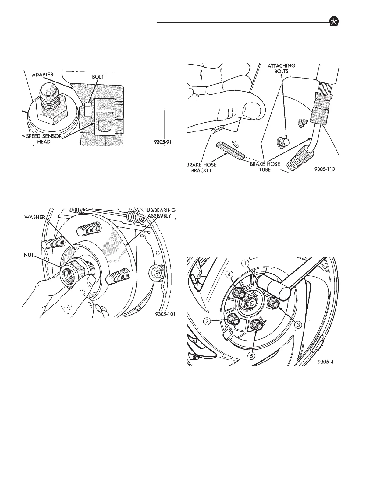
(7) If vehicle is equipped with Anti-Lock brakes.
Install the speed sensor head into the rear disc brake
adapter (Fig. 19). Torque speed sensor head to
adapter attaching bolt to 7 NIm (60 in. lbs.).
(8) Install the rear hub and bearing assembly on
the rear spindle. Install hub and bearing assembly
retaining washer and nut on spindle (Fig. 20).
Torque hub and bearing retaining nut to 168 NIm
(124 ft. lbs).
(9) If vehicle is equipped with rear disc brakes, in-
stall rear braking disc on hub. If vehicle is equipped
with rear drum brakes, install the brake drum on
hub.
(10) If vehicle is equipped with rear disc brakes,
install rear braking disc on hub. Carefully install
rear brake caliper over braking disc and install on
adapter. Tighten the caliper assembly to adapter
mounting bolts to 22 NIm (192 in. lbs.). Refer to Rear
Disc Brakes in Group 5 Brakes in this service man-
ual for required caliper installation procedure.
(11) If vehicle is equipped with rear drum brakes
install rear brake flex hose onto wheel cylinder and
support plate (Fig. 21). Torque the brake hose to
wheel cylinder tube nut to 17 NIm (145 in. lbs.).
Torque the brake hose bracket to support plate bolt
to8NIm (75 in. lbs).
(12) If vehicle has rear drum brakes, brake system
will require bleeding. Refer to Bleeding Brake Sys-
tem in the Service Adjustments Section of Group 5
Brakes in this service manual.
(11) Install wheel and tire assembly on vehicle.
Tighten the wheel mounting stud nuts in proper se-
quence (Fig. 22) until all nuts are torqued to half
specification. Then repeat the tightening sequence to
the full specified torque of 129 NIm (95 ft. lbs.).
(12) Lower vehicle to the ground.
(13) Check and reset rear wheel TOE to specifica-
tions if required.
REAR CROSSMEMBER
The L.H. platform vehicles are available with two
different rear crossmembers depending on the sus-
pension package the vehicle was built with. The
crossmembers visually look the same between the
standard and performance suspension packages, but
the mounting location for the lateral links is differ-
Fig. 19 Speed Sensor Head Installed In Adapter
Fig. 20 Rear Hub And Bearing Retaining Nut and
Washer Removal
Fig. 21 Brake Hose Bracket And Tube Nut
Fig. 22 Tightening Wheel Nuts
2 - 64 SUSPENSION AND DRIVESHAFTS








 To Next Page