INSTALL
(1) Install the stabilizer bar and isolator bushings
back into the vehicle as an assembly. Position stabi-
lizer bar so it is centered in the vehicle so it does not
contact other suspension components or vehicle body.
(2) Install the stabilizer bar attaching link onto
stabilizer bar. Install the stabilizer link to stabilizer
bar attaching nut (Fig. 2). Torque the stabilizer link
to stabilizer bar attaching nut to 95 NIm (70 ft. lbs.).
(3) Install fuel tank back in vehicle. Refer to
Group 14 Fuel, in this service manual for the re-
quired fuel tank installation procedure.
CAUTION: The sway bar bracket bolts must be re-
placed after loosening or removing them. Only use
original equipment bolts as replacements.
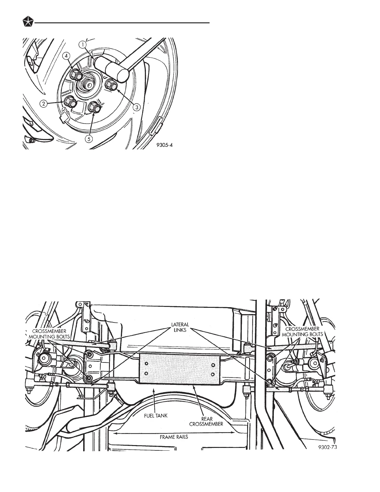
(4) Position crossmember on frame rails and install
the 4 crossmember to frame rail attaching bolts (Fig.
1). Torque the crossmember to frame rail attaching
bolts to 95 NIm (70 ft. lbs.).
(5) Remove transmission jack supporting fuel tank.
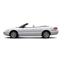
(6) Install wheel and tire assembly on vehicle.
Tighten the wheel mounting stud nuts in proper se-
quence (Fig. 3) until all nuts are torqued to half
specification. Then repeat the tightening sequence to
the full specified torque of 129 NIm (95 ft. lbs.).
(7) Lower vehicle to the ground.
(8) Check and reset rear wheel TOE to specifica-
tions if required.
SERVICING LATERAL LINKS
The lateral links are only serviced as complete as-
semblies. The isolator bushings used in the lateral
links are not serviced as separate components. The
left and right lateral links are serviced using differ-
ent procedures. See procedures below for the side of
the vehicle requiring service to the lateral links.
LEFT LATERAL LINKS
REMOVE
(1) Raise vehicle on jackstands or centered on a frame
contact type hoist. See Hoisting in the Lubrication and
Maintenance section of this manual, for the required
lifting procedure to be used for this vehicle.
(2) Remove left rear wheel and tire assembly from
the vehicle.
(3) Remove the nut and bolt attaching left lateral
links to the spindle (Fig. 2).
Fig. 3 Tightening Wheel Nuts
Fig. 1 Rear Suspension Lateral Links
SUSPENSION AND DRIVESHAFTS 2 - 67