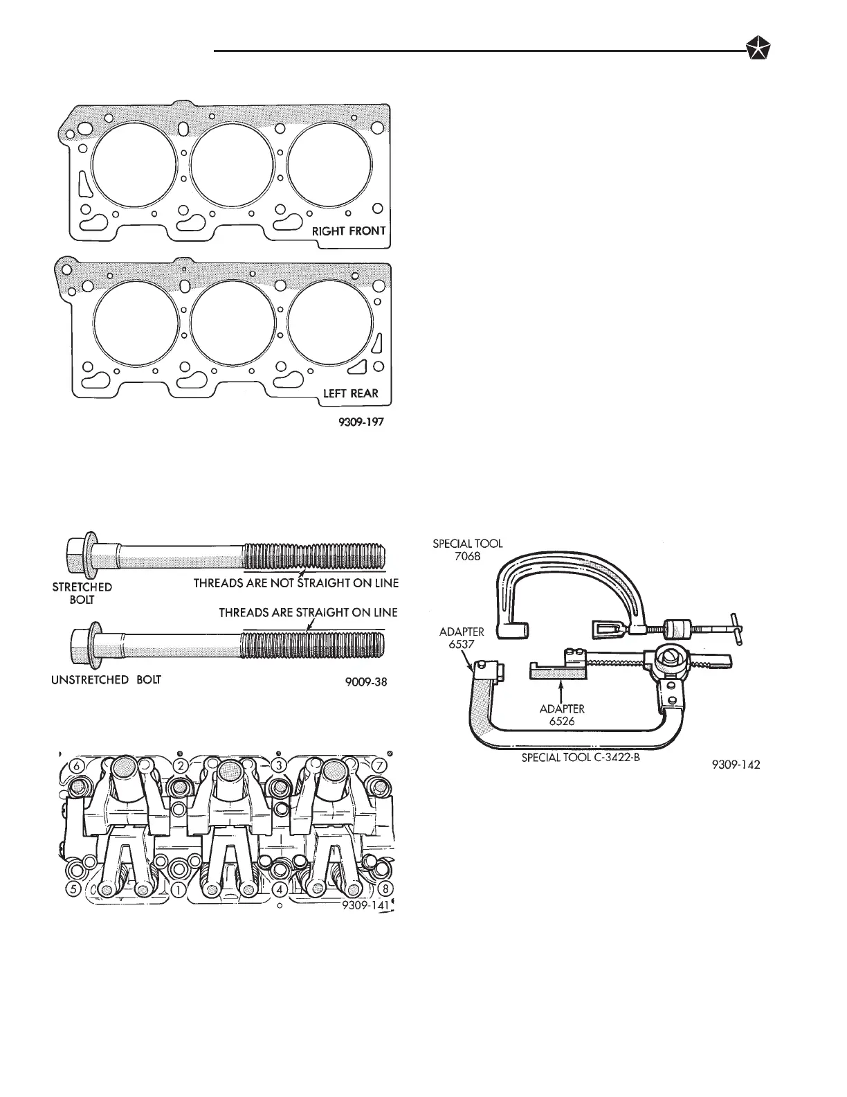
Necking can be checked by holding a scale or
straight edge against the threads. If all the threads
do not contact the scale the bolt should be replaced.
(1) Before installing the bolts the threads should
be oiled with engine oil.
(2) Install head gasket over locating dowels besure
the gasket is installed on the correct side (Fig. 18).
(3) Install cylinder head over dowels.
(4) Tighten the cylinder head bolts in the sequence
shown in (Fig. 20). Using the 4 step torque turn
method, tighten according to the following values:
• First All to 61 NIm (45 ft. lbs.)
• Second All to 88 NIm (65 ft. lbs.)
• Third All (again) to 88 NIm (65 ft. lbs.)
• Fourth + 1/4 Turn Do not use a torque wrench
for this step.
Bolt torque after 1/4 turn should be over 90 ft. lbs. If
not, replace the bolt.
VALVE SERVICE
VALVE AND VALVE SPRINGS
REMOVAL
(1) With cylinder head removed, compress valve
springs using the Valve Spring Compressors shown in
(Fig. 21).
(2) Remove valve retaining locks, valve spring re-
tainers, valve springs and valve spring seat/stem seal
assembly.
(3) Before removing valves, remove any burrs
from valve stem lock grooves to prevent damage
to the valve guides. Identify valves to insure instal-
lation in original location.
VALVE INSPECTION
(1) Clean valves thoroughly and discard burned,
warped and cracked valves.
(2) Measure valve stems for wear. Refer to specifica-
tions (Fig. 24).
Valve stems are chrome plated and should not
be polished.
(3) Remove carbon and varnish deposits from inside
of valve guides with a reliable guide cleaner.
(4) Measure valve stem guide clearance as follows:
(a) Install valve into cylinder head so it is 15mm
(.590 inch) off the valve seat. A small piece of hose
may be used to hold valve in place.
Fig. 18 Cylinder Head Gasket Identification
Fig. 19 Checking Bolts for Stretching (Necking)
Fig. 20 Cylinder Head Bolt Tightening Sequence
Fig. 21 Valve Spring Compressors
9 - 50 3.5L ENGINE