ASH RECEIVER/LAMP REMOVAL
(1) Remove lower slide out ash tray (Fig. 23).
(2) Remove two outboard screws from housing as-
sembly.
(3) Remove housing and pull rearward to disen-
gage from the forward locator.
(4) Ash receiver light is accessible by removing
socket from metal light housing and remove lamp
from socket.
(5) For installation, reverse above procedures.
CIGAR LIGHTER REMOVAL
(1) Remove lower slide out ash tray (Fig. 23).
(2) Remove two outboard screws from housing as-
sembly.
(3) Remove housing and pull rearward to disen-
gage from the forward locator.
(4) Ash receiver light is accessible by removing
socket from metal light housing and remove lamp
from socket.
(5) Disconnect the two cigar lighter wiring connec-
tors from cigar lighter. Unscrew shell and clamp as-
sembly to replace cigar lighter assembly.
(6) For installation, reverse above procedures.
ASH RECEIVER/LAMP REMOVAL—CHRYSLER
(1) Remove ash tray and lower center bezel (Fig.
23).
(2) Remove two housing mounting screws.
(3) Remove the housing and lamp.
(4) For installation, reverse above procedures.
CIGAR LIGHTER REMOVAL—CHRYSLER
(1) Remove ash tray and lower bezel (Fig. 23).
(2) Remove two housing mounting screws. Remove
the housing and lamp.
(3) Remove two A/C-Heater control mounting
screws. Move to the A/C-Heater control.
(4) Reach through the A/C-Heater control opening
to disconnect the two wire from the cigar lighter wir-
ing connectors. The cigar lighter shell can be un-
screw from the clamp so that the cigar lighter can be
removed.
(5) For installation, reverse above procedures.
GLOVEBOX DOOR/HANDLE REMOVAL
(1) Remove three screws at bottom of glovebox
door, open glovebox door and press sidewalls inboard
to remove door from panel (Fig. 25 and 26).
(2) Position the glovebox on cloth to protect paint.
Remove nine screws from backside of the door,
Chrysler 207 has eight screws. Then separate the in-
ner and outer door. Handle and latch can be removed
at this time.
GLOVEBOX LIGHT/SWITCH REMOVAL
(1) Open glovebox door and pull out glovebox light
switch from upper right corner of glovebox opening
on instrument panel (Fig. 25 and 26).
(2) Replace lamp or remove electrical connector to
replace switch.
(3) For installation, reverse above procedures.
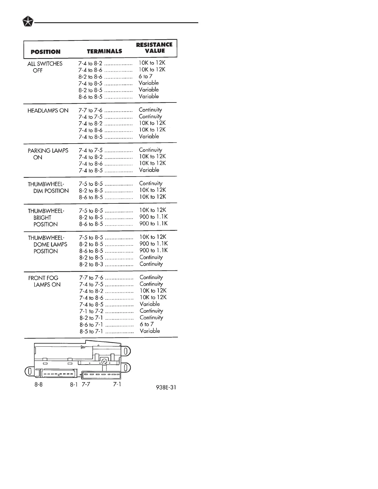
Fig. 27 Headlamp Switch Test
INSTRUMENT PANEL AND GAUGES 8E - 11