fuel mixture), the sensors produce voltages as low as
0.1 volt. When there is a lesser amount of oxygen
present (rich air-fuel mixture) the sensor produces a
voltage as high as 1.0 volt. By monitoring the oxygen
content and converting it to electrical voltage, the
sensor acts as a rich-lean switch.
The oxygen sensors are equipped with a heating
element. The heating element keeps the sensor at
proper operating temperature during all operating
modes. Maintaining correct sensor temperature at all
times allows the system to enter into closed loop
operation sooner. Also, it allows the system to remain
in closed loop operation during periods of extended
idle.
In Closed Loop operation the PCM monitors the inputs
from the heated oxygen sensors (along with
other inputs) and adjusts the injector pulse width
accordingly. During Open Loop operation the PCM
ignores the inputs fromthe heated oxygen sensors. The
PCM adjusts injector pulse width based on prepro-
grammed (fixed) values and inputs from other sensors.
REMOVAL—3.3L ENGINE
The 3.3Lengine uses two heated oxygen sensors, one
in each exhaust manifold. The sensors point toward the
engine block. For access to the right side sensor,
remove the air cleaner resonator and hose.
(1) Disconnect electrical connector.
(2) Use a crow-foot wrench or open end wrench to
remove heated oxygen sensor (Fig. 7).
After removing the sensor, the exhaust manifold
threads must be cleaned with an 18 mm X 1.5 + 6E tap.
If reusing the original sensor, coat the sensor threads
with an anti-seize compound such as Loctitet 771-64 or
equivalent. New sensors have compound on the
threads and do not require an additional coating.
Tighten the sensor to 28 NIm (20 ft. lbs.) torque.
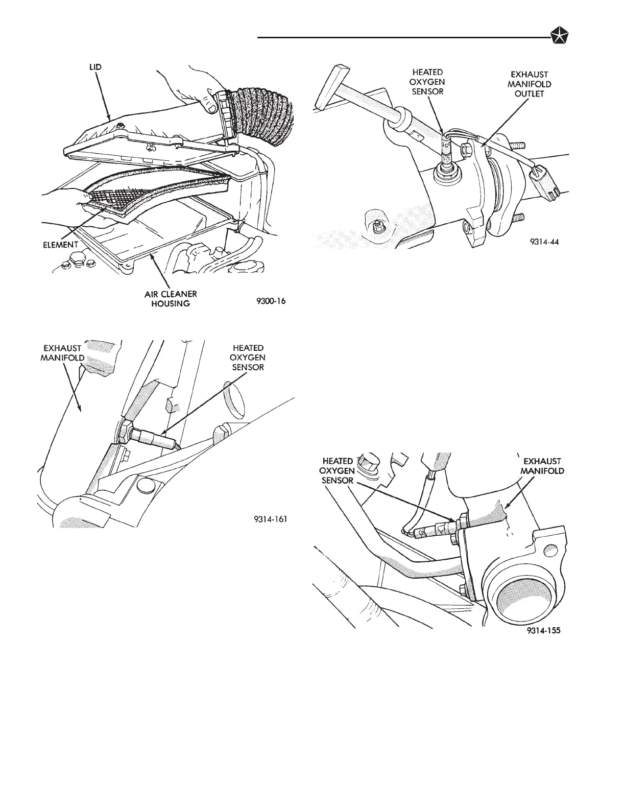
Fig. 4 Air Cleaner Housing and Element
Fig. 5 Heated Oxygen Sensor—3.3L Engine
Fig. 6 Heated Oxygen Sensor—3.5L Engine
Fig. 7 Heated Oxygen Sensor
Removal/Installation—3.3L Engine
25 - 10 EMISSION CONTROL SYSTEMS