and discard. Remove the sealing boot from the outer
C/V joint housing and slide it down the interconnecting
shaft.
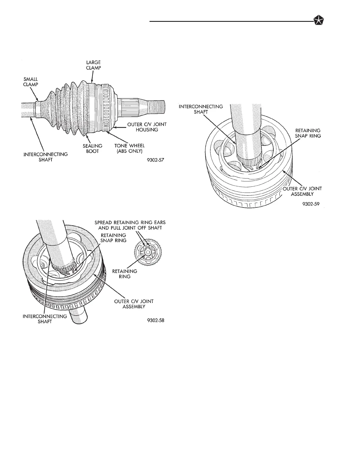
(3) Wipe away grease to expose outer C/V joint to
interconnecting shaft retaining ring (Fig. 2). Spread
ears apart on C/V joint assembly to interconnecting
shaft retaining snap ring (Fig. 2). Slide outer C/V joint
assembly off end of interconnecting shaft.
(4) Slide failed sealing boot off the interconnecting
shaft.
(5) Thoroughly clean and inspect outer C/V joint
assembly and interconnecting joint for any signs of
excessive wear. If any parts show signs of excessive
wear, the driveshaft assembly will require re-
placement. Component parts of the L.H. platform
driveshaft assemblies are not serviceable.
INSTALL
(1) Slide a new seal boot to interconnecting shaft
retaining clamp, onto the interconnecting shaft. Then
slide the replacement outer C/V joint assembly seal-
ing boot onto the interconnecting shaft.
(2) Install outer C/V joint assembly onto intercon-
necting shaft. Joint is installed on interconnecting
shaft, by pushing interconnecting shaft into outer
C/V joint, until retaining snap ring is seated in
groove on interconnecting shaft (Fig. 3). Be sure the
snap ring is fully seated into groove on interconnect-
ing shaft.
(3) Distribute 1/2 the amount of grease provided in
seal boot service package (DO NOT USE ANY
OTHER TYPE OF GREASE) into outer C/V joint as-
sembly housing. Put the remaining amount into the
sealing boot.
(4) Position the sealing boot over the boot retain-
ing groove on the interconnecting shaft. Install seal
boot retaining clamp evenly on sealing boot.
(5) Clamp sealing boot on interconnecting shaft us-
ing Crimper, Special Tool C-4975 and the following
procedure. Place crimping tool C-4975 over bridge of
clamp (Fig. 4). Tighten nut on crimping tool C-4975
until jaws on tool are closed completely together, face
to face (Fig. 5).
CAUTION: Seal must not be dimpled, stretched or
out of shape in any way. If seal is NOT shaped cor-
rectly, equalize pressure in seal and shape it by
hand.
(6) Position the sealing boot into the boot retaining
groove on the outer C/V joint housing (Fig. 6). Install
seal boot retaining clamp evenly on sealing boot.
(7) Clamp sealing boot onto outer C/V joint hous-
ing using Crimper, Special Tool C-4975 and the fol-
lowing procedure. Place crimping tool C-4975 over
bridge of clamp (Fig. 4). Tighten nut on crimping tool
C-4975 until jaws on tool are closed completely to-
gether, face to face (Fig. 5).
Fig. 3 Outer C/V Joint Installed On Interconnecting
Shaft
Fig. 1 Outer C/V Joint Sealing Boot Clamps
Fig. 2 Outer C/V Joint Removal From Intercon
ecting Shaft
2 - 50 SUSPENSION AND DRIVESHAFTS
 Loading...