LOWER CONTROL ARM SERVICE
The lower control arm if damaged, is serviced only as
a complete component. Do not attempt to repair or
straighten a broken or bent lower control arm.
The only serviceable components of the lower control
arm are, the pivot bushing, ball joint seal and tension
strut bushing. The service procedure to replace these
components is detailed in the specific component sec-
tions of this group.
REMOVAL (ASSEMBLY)
(1) Raise vehicle on jackstands or centered on a
frame contact type hoist. See Hoisting in the Lubrica-
tion and Maintenance section of this manual, for the
required lifting procedure to be used for this vehicle.
(2) Remove the wheel and tire assembly from the
vehicle.
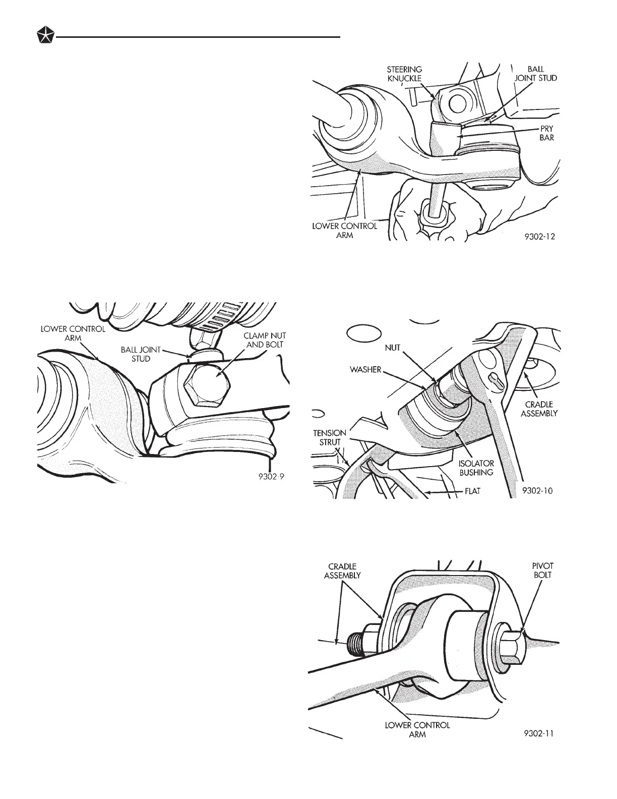
(3) Remove the ball joint stud to steering knuckle
clamp nut and bolt (Fig. 1).
CAUTION: When lower control is separated from
steering knuckle, do not let ball joint seal hit up
against steering knuckle. If ball joint seal hits steer-
ing knuckle, seal damage may occur. If ball joint seal
becomes torn, replace seal before assembling lower
control arm to knuckle.
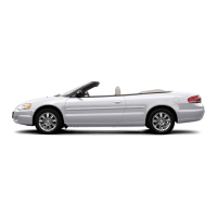
(4) Carefully insert a pry bar between lower control
arm and steering knuckle (Fig. 2). Push down on pry
bar to separate ball joint stud from steering knuckle
(Fig. 2). Note: Use caution when separating ball
joint stud from steering knuckle so ball joint seal
does not get cut.
CAUTION: Pulling steering knuckle out from vehicle
after releasing from ball joint can separate inner C/V
joint. See Driveshafts.
(5) Remove tension strut to cradle attaching nut and
washer from end of tension strut (Fig. 3). When remov-
ing tension strut nut, keep strut from turning
by holding tension strut at flat using open end wrench
(Fig. 3). Discard tension strut to cradle retaining
nut. A NEW tension strut to cradle nut must be
used when installing tension strut.
(6) Loosen and remove lower control arm pivot bush-
ing to cradle assembly pivot bolt (Fig. 4).
Fig. 4 Lower Control Arm Pivot Bolt
Fig. 1 Control Arm To Steering Knuckle Attachment
Fig. 2 Separating Ball Joint From Steering Knuckle
Fig. 3 Tension Strut To Cradle Mounting
SUSPENSION AND DRIVESHAFTS 2 - 13