FRAME AND BUMPERS
CONTENTS
page page
ENGINE CRADLE CROSSMEMBER .......... 2
FRAME DIMENSIONS ..................... 3
FRONT BUMPER FASCIA ................. 1
FRONT BUMPER REINFORCEMENT ......... 1
GENERAL INFORMATION .................. 1
REAR BUMPER FASCIA ................... 2
GENERAL INFORMATION
In this section, references are made to Vehicle
Family (Body) codes. To determine the vehicle family
identification code, refer to the Introduction Group at
the front of this manual.
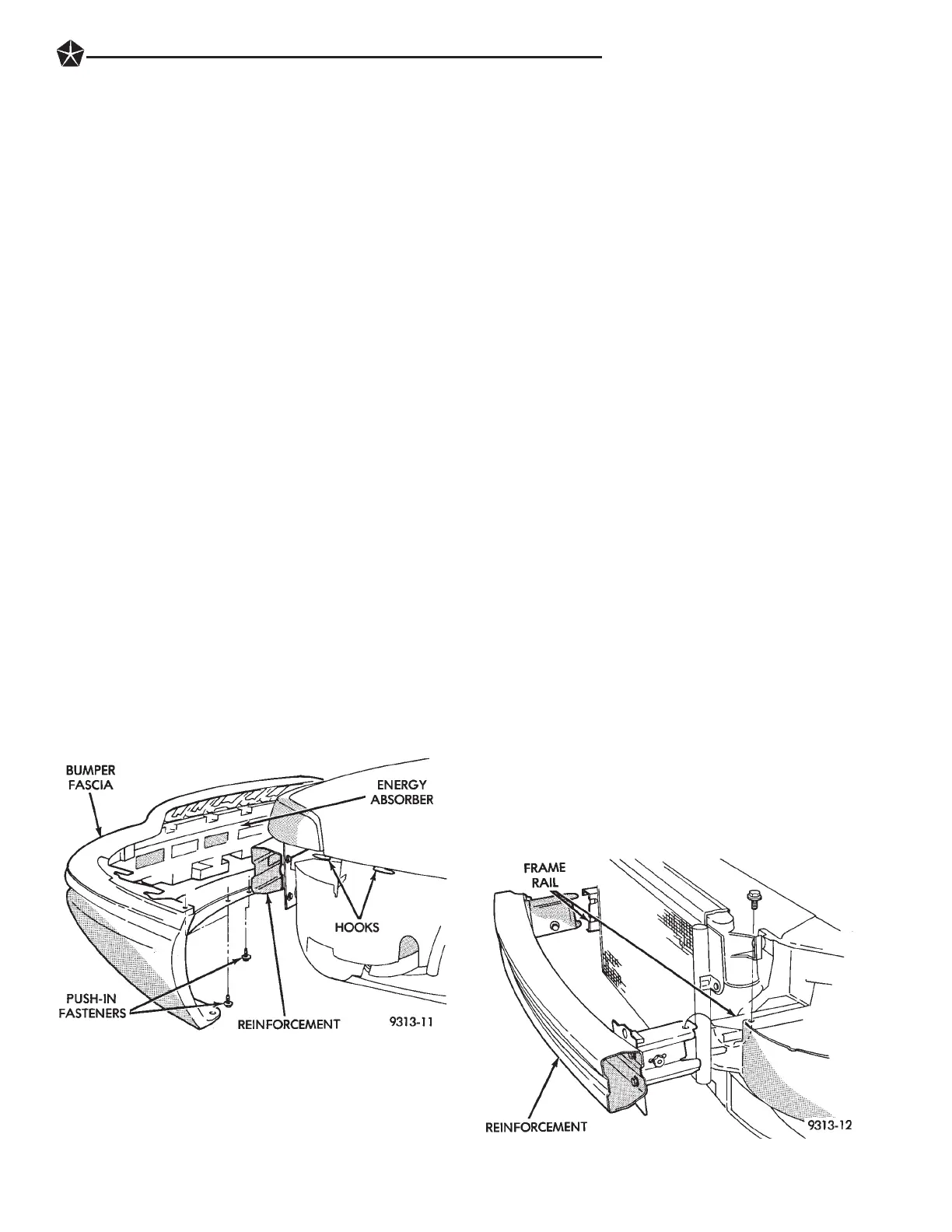
FRONT BUMPER FASCIA
REMOVAL (FIG. 1)
(1) Release hood latch and open hood.
(2) Remove front wheelhouse splash shields as nec-
essary to gain access to fascia fasteners. Refer to
Group 23, Body for proper procedures.
(3) Remove push-in fasteners holding bottom of
fascia to radiator closure panel.
(4) Disengage fog lamp wire connector from body
wire harness, if equipped.
(5) Remove push-in fasteners holding fascia to
front fenders.
(6) Disengage fascia from hooks on bottom of front
fenders.
(7) Separate fascia from vehicle.
INSTALLATION
(1) Place fascia in position on vehicle.
(2) Engage fascia to hooks on bottom of front fend-
ers.
(3) Install push-in fasteners to hold fascia to front
fenders.
(4) Engage fog lamp wire connector to body wire
harness, if equipped.
(5) Install push-in fasteners to hold bottom of fas-
cia to radiator closure panel.
(6) Install front wheelhouse splash shields.
FRONT BUMPER REINFORCEMENT
REMOVAL (FIG. 2)
(1) Remove front fascia.
(2) Remove bolts holding top of bumper reinforce-
ment adapter to frame rail.
(3) Loosen bolts holding inside of bumper rein-
forcement to frame rail.
(4) Pull reinforcement forward.
(5) Separate reinforcement from vehicle.
INSTALLATION
(1) Place reinforcement in position on front of ve-
hicle.
(2) Push reinforcement adapters rearward into
ends of frame rails.
(3) Tighten bolts to hold inside of bumper rein-
forcement to frame rail.
(4) Install bolts to hold top of bumper reinforce-
ment adapters to frame rail.
(5) Install front fascia.
Fig. 1 Front bumper Fascia
Fig. 2 Front Bumper Reinforcement
FRAME AND BUMPERS 13 - 1

 Loading...