REFACING VALVES AND VALVE SEATS
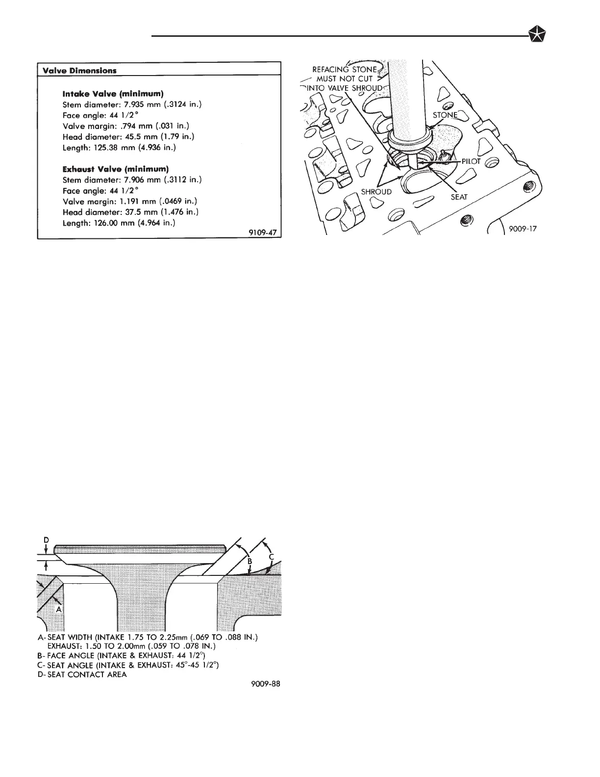
The intake and exhaust valves have a 44-1/2 to 45
degree face angle. The valve seats have a 45 to 45-
1/2 degree face angle. The valve face and valve seat
angles are shown in (Fig. 20).
VALVES
(1) Inspect the remaining margin after the valves
are refaced Refer to specifications (Fig. 19).
VALVE SEATS
CAUTION: Do not un-shroud cylinder head from
around the valve during valve seat refacing (Fig.
21).
(1) When refacing valve seats, it is important that
the correct size valve guide pilot be used for reseat-
ing stones. A true and complete surface must be ob-
tained.
(2) Measure the concentricity of valve seat using
dial indicator. Total runout should not exceed
.051mm (.002 inch) total indicator reading.
(3) Inspect the valve seat with Prussian blue to de-
termine where the valve contacts the seat. To do
this, coat valve seat LIGHTLY with Prussian blue
then set valve in place. Rotate the valve with light
pressure. If the blue is transferred to the center of
valve face, contact is satisfactory. If the blue is trans-
ferred to top edge of valve face,lower valve seat with a
15 degree stone. If the blue is transferred to the bottom
edge of valve face raise valve seat with a 65 degrees
stone.
Valve seats which are worn or burned can be
reworked, provided that correct angle and seat
width are maintained. Otherwise cylinder head
must be replaced.
(4) When seat is properly positioned the width of
intake seats should be 1.75 to 2.25mm (0.69 to .088
inch) The width of the exhaust seats should be 1.50 to
2.00mm (.059 to .078 inch) (Fig. 20)
(5) Check the valve spring installed height after
refacing the valve and seat (Fig. 23).
TESTING VALVE SPRINGS
Whenever valves have been removed for inspection,
reconditioning or replacement, valve springs should be
tested (Fig. 22). As an example; the compression
length of the spring to be tested is 33.34mm (1-5/16
inches). Turn table of Tool C-647 until surface is in line
with the 33.34mm (1-5/16 inch) mark on the threaded
stud and the zero mark on the front. Place spring over
stud on the table and lift compressing lever to set tone
device. Pull on torque wrench until ping is heard. Take
reading on torque wrench at this instant. Multiply this
reading by two. This will give the spring load at test
length. Fractional measurements are indicated on the
table for finer adjustments. Refer to specifications to
obtain specified height and allowable tensions. Discard
the springs that do not meet specifications.
Fig. 19 Valve Dimensions
Fig. 20 Valve Seats
Fig. 21 Refacing Valve Seats
9 - 14 3.3L ENGINE

 Loading...