REAR WHEEL TOE SETTING PROCEDURE
Rear Wheel alignment adjustments can only be
made for the Toe In setting on the L.H. platform
vehicles.
Toe is measured in degrees or inches and is the
distance the front edges of the tires are closer (or
farther apart) than the rear edges. See Front Wheel
Drive Specifications for Toe settings.
REAR WHEEL TOE ADJUSTMENT
(1) Prepare vehicle as described in the Pre-
Alignment procedure.
(2) Loosen lateral link, adjustment link jamnuts
(Fig. 1). Rotate adjustment links as required to set rear
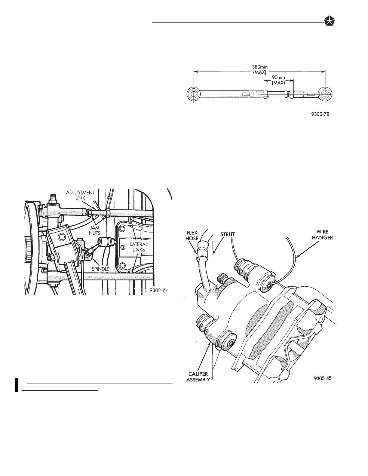
wheel Toe to specifications. Do not exceed the maxi-
mum length dimensions of the lateral links
shown in (Fig. 2). Both dimensions must be
checked to ensure they do not exceed maximums
allowed.
CAUTION: When setting rear (Toe In( on vehicle. The
maximum lengths of the adjustable lateral link at the
locations shown in (Fig. 2) must not be exceeded. If
these maximum lengths are exceeded, inadequate
retention of adjustment link to the inner and outer link
may result. Ensure that the adjustment sleeve jam
nuts are torqued to the required specifications when
the Toe setting procedure is completed.
(4) Tighten lateral link, adjustment link locknuts to
65 NIm (48 ft. lbs.) torque.
SERVICING REAR STRUTS
REMOVAL
(1) Raise vehicle on jackstands or centered on a
frame contact type hoist. See Hoisting in the Lubrica-
tion and Maintenance section of this manual, for the
required lifting procedure to be used for this vehicle.
(2) Remove the rear wheel and tire assembly from
the vehicle.
(3) If vehicle is equipped with rear disc brakes,
remove the rear caliper assembly from the adapter.
Refer to Rear Disk Brakes in Group 5 Brakes of this
Service manual for required caliper removal proce-
dure. After removing caliper assembly store caliper by
hanging it from vehicle (Fig. 1). Do not let rear caliper
assembly hang from flexible brake hose. If vehicle is
equipped with reardrum brakes, remove thebrake flex
hose bracket from the support plate and wheel cylinder
(Fig. 2).
(4) If vehicle is equipped with rear disc brakes,
remove rear braking disc from hub.
(5) If vehicle is equipped with rear disc brakes.
Remove the speed sensor cable routing tube on trailing
arm and the routing bracket on the trailing arm
bracket to spindle (Fig. 3). If spindle and trailing
arm assembly is lowered from strut with the
Fig. 1 Rear Wheel Toe Adjustment At Lateral Links
Fig. 2 Lateral Link Maximum Length Dimensions
Fig. 1 Storing Rear Caliper Assembly
2 - 54 SUSPENSION AND DRIVESHAFTS
1993 Concorde/Intrepid/Vision
Publication No. 81-270-3140
TSB 02-07-92 November 16, 1992