speed sensor cable attached damage to speed
sensor cable may occur.
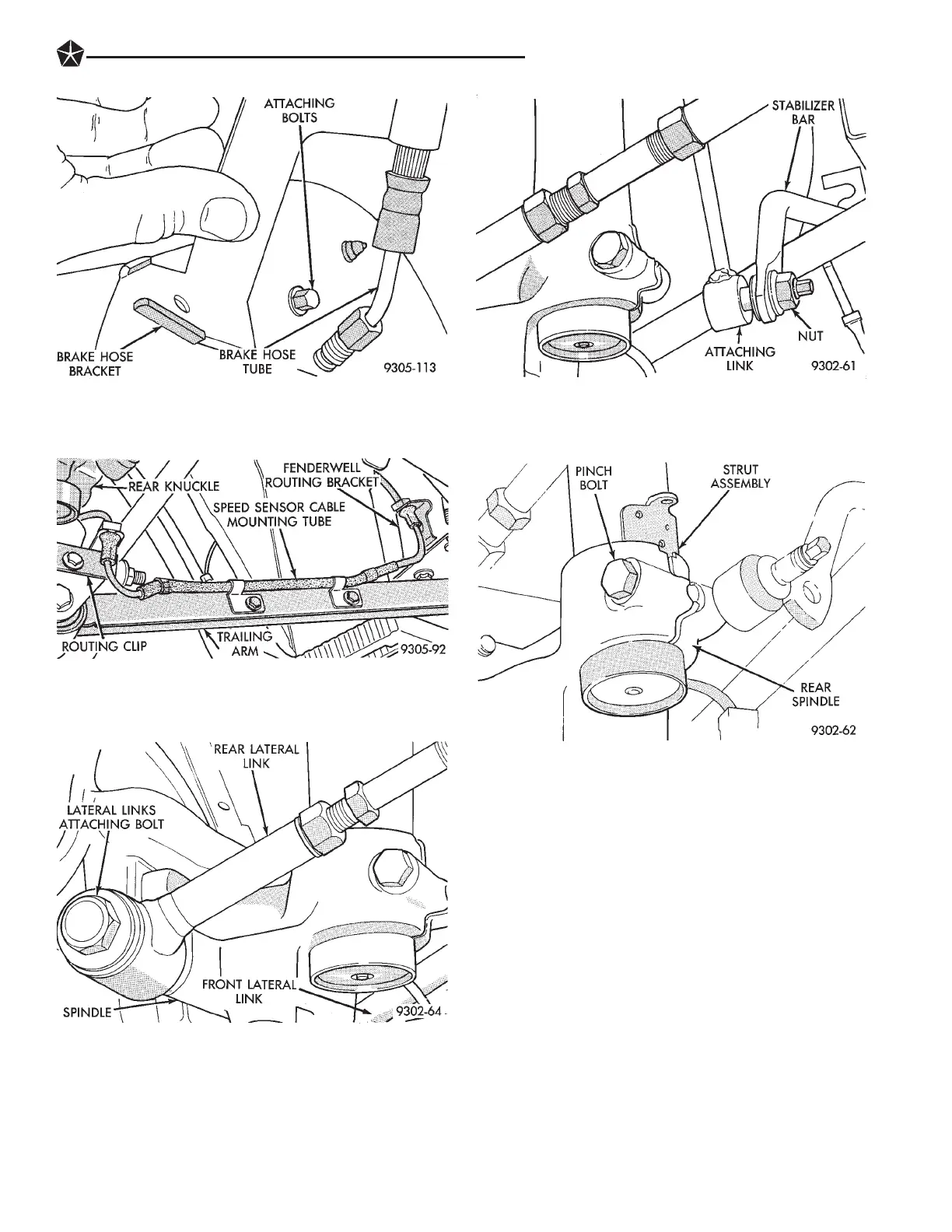
(6) Remove the bolt (Fig. 4) attaching the lateral
links to the rear spindle assembly.
(7) Remove the rear strut assembly to stabilizer bar
attaching link, at the stabilizer bar (Fig. 5). Hold hex
on attaching link stud while breaking nut loose. This
will keep bushing in attaching link from slipping. The
attaching link does not have to be removed from strut
assembly.
(8) Loosen and fully remove, the rear spindle to
strut assembly pinch bolt (Fig. 6).
(9) Insert a center punch into the hole on the spin-
dle (Fig. 7). Center punch must be tapped into spin-
dle until jammed into hole. This will spread spindle
casting allowing it to be removed from strut assem-
bly. Do not punch hole in strut with center punch.
(10) Using a hammer, tap on top surface of spindle
driving it down and off the end of the strut assembly
(Fig. 8).
(11) Let the rear spindle and assembled compo-
nents hang from trailing arm (Fig. 9) while strut as-
sembly is out of the vehicle.
(12) Lower vehicle.
(13) To remove the rear upper strut mount from
the vehicle, access the upper strut mount to strut
tower attaching nuts from the trunk of the vehicle.
(14) Remove the 3 rear strut assembly to body
mounting nuts, and remove strut assembly from ve-
hicle.
Fig. 5 Attachment Link To Stabilizer Bar Attaching
Fig. 6 Spindle To Strut Assembly Pinch Bolt
Fig. 2 Brake Hose Bracket And Tube
Fig. 3 Speed Sensor Routing Tube And Bracket
Fig. 4 Lateral Links To Spindle Attaching Bolt
SUSPENSION AND DRIVESHAFTS 2 - 55
 Loading...