The bearing shells must be installed with the tangs
inserted into the machined grooves in the rods and
caps. Install cap with the tangs on the same side as the
rod.
Limits of taper or out-of-round on any crankshaft
journals should be held to .025mm (.001 inch). Bear-
ings are available in .025mm (.001 inch), .051mm (.002
inch),.076mm (.003 inch), .254mm (.010 inch) and
.305mm (.012 inch) undersize. Install the bearings
in pairs. Do not use a new bearing half with an
old bearing half. Do not file the rods or bearing
caps.
(1) Follow procedure specified in the Standard Ser-
vice Procedure Section for Measuring Main Bearing
Clearance and Connecting Rod Bearing Clearance
(Fig. 16).
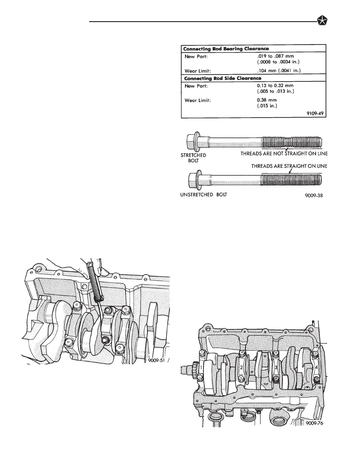
The rod bearing bolts should be examined be-
fore reuse. If the threads are necked down the
bolts should be replaced (Fig. 19).
Necking can be checked by holding a scale or straight
edge against the threads. If all the threads do not
contact the scale the bolt should be replaced.
(2) Before installing the nuts the threads should be
oiled with engine oil.
(3) Install nuts on each bolt finger tight then alter-
nately torque each nut to assemble the cap properly.
(4) Tighten the nuts to 54 NIm PLUS 1/4 turn (40 ft.
lbs. PLUS 1/4 turn).
(5) Using a feeler gauge, check connecting rod side
clearance (Fig. 17). Refer to (Fig. 18) for specifications.
CRANKSHAFT SERVICE
CRANKSHAFT MAIN BEARINGS
Bearing caps are not interchangeable and should be
marked at removal to insure correct assembly. (Fig. 1)
Upper and lower bearing halves are NOT interchange-
able. Lower main bearing halves of 1, 3 and 4 are
interchangeable. Upper main bearing halves of 1, 3
and 4 are interchangeable.
CRANKSHAFT MAIN JOURNALS
The crankshaft journals should be checked for excessive
wear, taper and scoring. (Fig. 6) Limits of taper or
out-of-round on any crankshaft journals should be held to
.025mm (.001 inch). Journal grinding should not exceed
.305mm (.012 inch) under the standard journal diameter.
Do NOT grind thrust faces of Number 2 main bearing. Do
NOT nick crank pin or bearing fillets. After grinding,
remove rough edges from crankshaft oil holes and clean
out all passages.
CAUTION: With the nodular cast iron crankshafts
used it is important that the final paper or cloth polish
after any journal regrind be in the same direction as
normal rotation in the engine.
Fig. 17 Checking Connecting Rod Side Clearance
Fig. 18 Connecting Rod Specifications
Fig. 19 Check for Stretched Bolts
Fig. 1 Main Bearing Cap Identification
9 - 26 3.3L ENGINE
1993 Concorde/Intrepid/Vision
Publication No. 81-270-3140
TSB 09-17-92 November 2, 1992

 Loading...