• Dust shield
• Mount assembly
• Jounce Bumper
• Lower Spring Isolator
• Shaft Nut
(1) Remove strut assembly requiring service from
the vehicle. Refer to Strut Assembly Removal in Ser-
vicing Rear Struts, in this section of the service man-
ual.
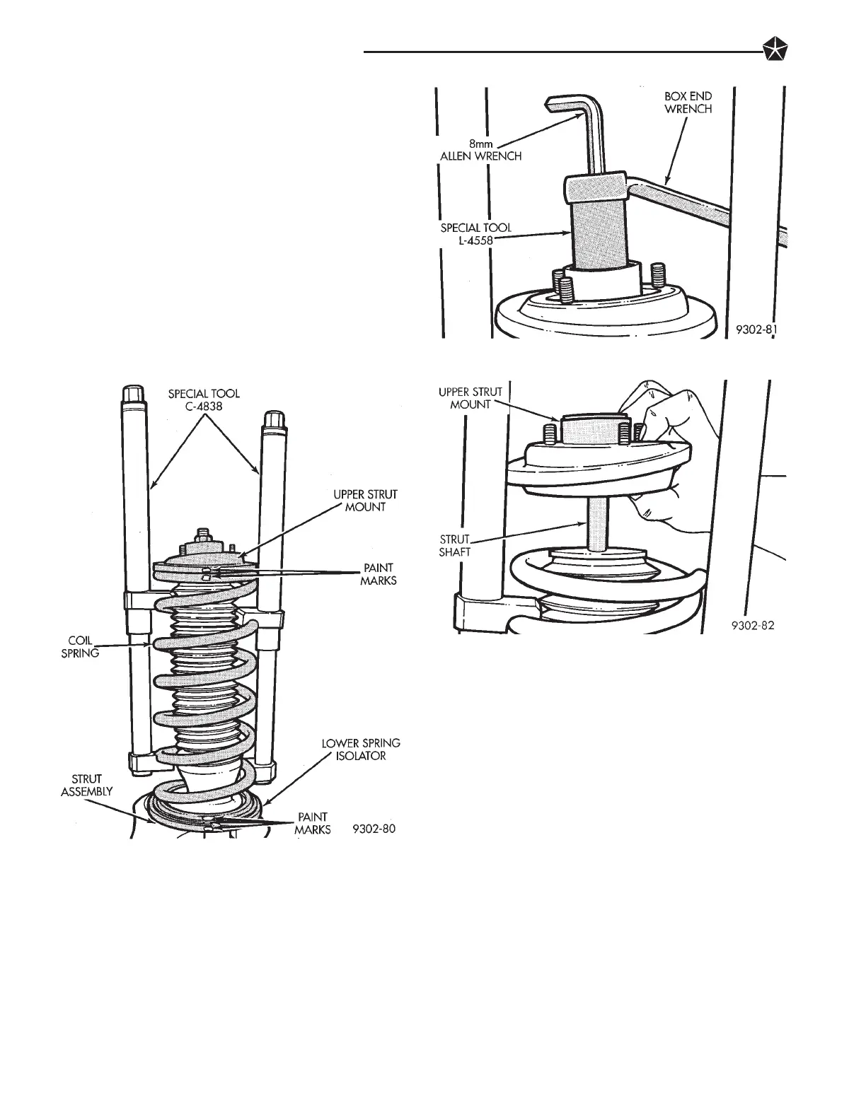
(2) Position strut assembly in a vise (Fig. 1). Using
paint or equivalent, mark the strut unit, lower
spring isolator, spring and upper strut mount for in-
dexing of the parts at assembly.
(3) Position Spring Compressors, Special Tool
C-4838 on the strut assembly spring (Fig. 1). Com-
press coil spring until all load is removed from upper
strut mount assembly.
(4) Install Strut Rod Socket, Special Tool, L-4558
on strut shaft nut (Fig. 2). Usea8mmallen wrench
inserted into end of strut shaft to keep strut shaft
from turning (Fig. 2). Remove strut shaft nut from
shaft.
(5) Remove upper strut mount assembly from strut
shaft (Fig. 3).
(6) Remove the coil spring and spring compressor
as an assembly from the strut (Fig. 4).
(7) Remove the plate, dust shield and jounce
bumper as an assembly from the strut unit (Fig. 5).
(8) Remove lower spring isolator from strut assem-
bly (Fig. 6).
Inspect all disassembled components for signs of
abnormal wear or failure replacing any components as
required. Inspect strut unit for signs of abnormal oil
leakage and for loss of gas charge. To check for loss of
gas charge in strut unit. Push strut shaft into body of
strut and release, strut shaft should return to its fully
extended position. If strut shaft does not return to its
fully extended position replace strut unit.
STRUT REASSEMBLY
(1) Install original or new, lower spring isolator on
strut unit (Fig. 6). If installing original isolator align
paint marks on isolator and strut unit.
(2) Install jounce bumper into dust shield (Fig. 7).
Install plate on top of dust shield and into jounce
bumper (Fig. 8).
(3) Install the dust shield, jounce bumper and top
plate as an assembly onto the strut unit (Fig. 5).
(4) Lower the coil spring and compressor onto the
strut unit (Fig. 4) Align the paint mark on the spring
with the paint mark on the strut unit (Fig. 1).
Fig. 1 Compressing Strut Assembly Coil Spring
Fig. 2 Removing Strut Shaft Nut
Fig. 3 Upper Strut Mount Removal
2 - 58 SUSPENSION AND DRIVESHAFTS








 To Next Page