(2) Remove valve body assembly from transaxle. Re-
fer to Valve Body in this section for removal procedure.
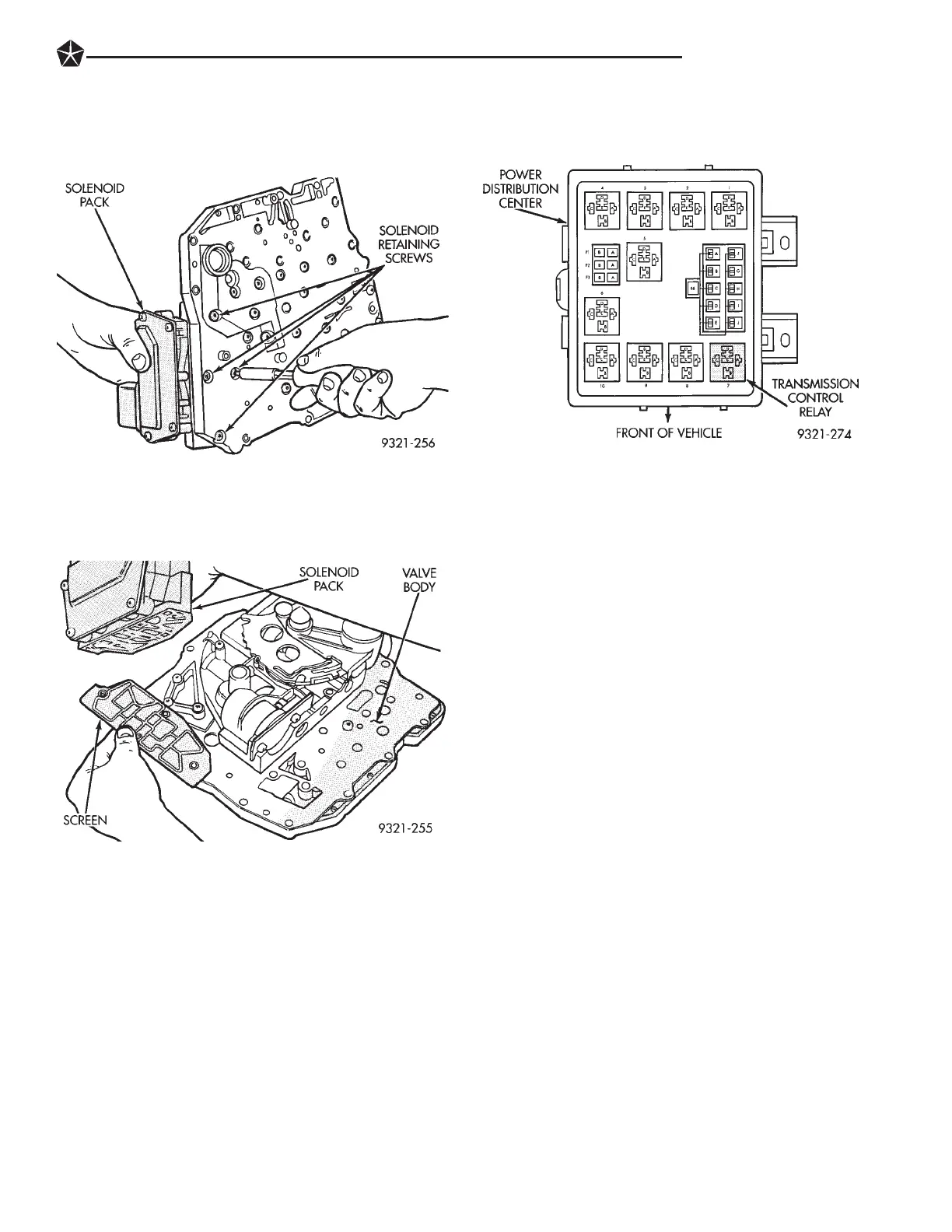
(3) Remove solenoid retaining screws from solenoid
(Fig. 2).
(4) Remove solenoid and screen from valve body
(Fig. 3).
To install, reverse removal procedure.
TRANSMISSION CONTROL RELAY
The transmission control module controls power to
the solenoid pack through the transmission control
relay. The relay is located in the power distribution
center on the left strut tower.
TEST
Refer to the 1993 42LE Transaxle Diagnostic Pro-
cedures Manual for test procedures.
REMOVAL AND INSTALLATION
(1) Open hood and locate power distribution center
in the engine compartment.
(2) Remove power distribution center plastic cover.
(3) Pull relay out of power distribution center (Fig.
4).
To install, reverse removal procedure.
TRANSMISSION CONTROL MODULE
The transmission control module is located in the
engine compartment between the left front fender and
the battery. It is held in place by four mounting screws.
The battery must be moved to gain access to the
transmission control module.
If the transmission control module has been
replaced, refer to ‘‘Quick Learn Procedure’’. This
program will allow the transmission control
module to learn the characteristics of the ve-
hicle.
REMOVAL
(1) Loosen battery hold-down clamp and slide the
battery to the right.
(2) Loosen 60 way retaining screw, located in the
center of the 60 way connector. Then disconnect the 60
way connector on transmission control module.
(3) Remove transmission control module mounting
screws and lift module from vehicle.
INSTALLATION
(1) Install transmission control module and tighten
mounting screws.
(2) Install 60 way connector. Then tighten 60 way
retaining screw to 4 NIm (35 in. lbs.).
(3) Place battery back in its original location and
tighten battery hold-down clamp.
BACK UP LAMP DIAGNOSIS
The back-up lamps are controlled by the Manual
Valve Lever Position Sensor (MVLPS). The following
flow chart will assist in diagnosing the back-up lamp
system. Refer to Manual Valve Lever Position Sensor
in this section for removal procedure.
Fig. 3 Solenoid and Screen removal
Fig. 2 Solenoid Retaining Screws
Fig. 4 Transmission Control Relay Location
TRANSAXLE 21 - 21