INSTALLATION
(1) Place cable in position on vehicle.
(2) Push cable through access hole in dash panel
under the brake master cylinder, into engine com-
partment. Rout cable assembly through engine com-
partment toward the latch.
(3) Install release cable rubber grommet into ac-
cess hole in dash panel.
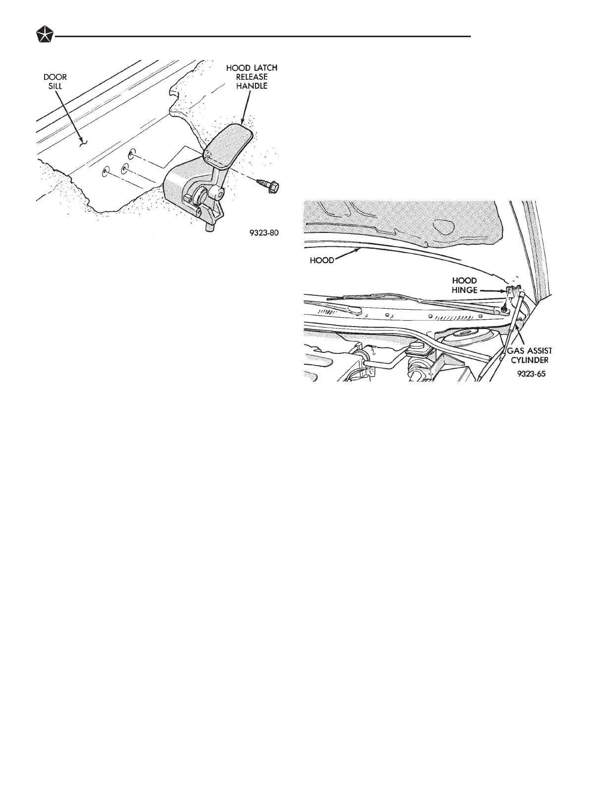
(4) Install bolts to hold hood latch release cable
handle to the floor pan kick-up below the door open-
ing (Fig. 5).
(5) Install left front door sill trim cover.
(6) Connect hood release cable casing and cable
end to hood latch assembly (Fig. 4). Refer to Hood
Latch procedure in this section.
(7) Verify hood latch operation before closing hood.
HOOD
REMOVAL (FIG. 6)
(1) Raise hood to full up position.
(2) Disengage under hood lamp wire connector
from engine compartment wire harness.
(3) Mark all bolt and hinge attachment locations
with a grease pencil or other suitable device to pro-
vide reference marks for installation. When install-
ing hood, align all marks and secure bolts. The hood
should be aligned to 4 mm (0.160 in.) gap to the front
fenders and flush across the top surfaces along fend-
ers.
(4) Remove the top bolts holding hood to hinge and
loosen the bottom bolts until they can be removed by
hand.
(5) With assistance from a helper at the opposite
side of the vehicle to support the hood, remove bot-
tom bolts holding hood to hinge. Separate the hood
from the vehicle.
INSTALLATION
(1) Place hood in position on vehicle. With assis-
tance from a helper at the opposite side of the vehicle
to support the hood, install bottom bolts to hold hood
to hinge finger tight.
(2) Install top bolts to hold hood to hinge finger
tight.
(3) Position bolts at marks and tighten bolts. The
hood should be aligned to 4 mm (0.160 in.) gap to the
front fenders and flush across the top surfaces along
fenders.
(4) Engage under hood lamp wire connector to en-
gine compartment wire harness.
(5) Verify hood operation and alignment.
HOOD HINGE
REMOVAL (FIG. 7)
(1) Support hood on the side that requires hinge
replacement.
(2) Mark all bolt and hinge attachment locations
with a grease pencil or other suitable device to pro-
vide reference marks for installation. When install-
ing hood hinge, align all marks and secure bolts. The
hood should be aligned to 4 mm (0.160 in.) gap to the
front fenders and flush across the top surfaces along
fenders. Shims can be added or removed under hood
hinge to achieve proper hood height.
(3) Remove bolts holding hood to hinge.
(4) Remove bolts holding hood hinge to front
fender flange and separate hinge from vehicle. If nec-
essary, paint new hinge before installation.
INSTALLATION
(1) If necessary, paint new hinge before installa-
tion.
(2) Place hinge in position on vehicle.
(3) Install bolts to hold hood hinge to front fender
flange.
(4) Install bolts to hold hood to hinge.
(5) Align all marks and secure bolts. The hood
should be aligned to 4 mm (0.160 in.) gap to the front
fenders and flush across the top surfaces along fend-
Fig. 5 Hood Release Handle
Fig. 6 Hood
BODY 23 - 9












 To Next Page