HUB AND BEARING ASSEMBLY
This unit is serviced only as a complete assembly.
It is mounted to the steering knuckle by 3 mounting
bolts that are removed from the rear of the steering
knuckle.
REMOVAL
(1) Raise vehicle on jackstands or centered on a
frame contact type hoist. See Hoisting in the Lubri-
cation and Maintenance section of this manual, for
the required lifting procedure to be used for this ve-
hicle.
(2) Remove the front wheel and tire assembly from
the vehicle.
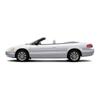
(3) Remove the front caliper assembly from the
front steering knuckle assembly (Fig. 1). Refer to
Front Disc Brake Service in the Brake Section of this
service manual for caliper removal procedure.
(4) Remove front braking disk (rotor) from hub, by
pulling it straight off wheel mounting studs (Fig. 2).
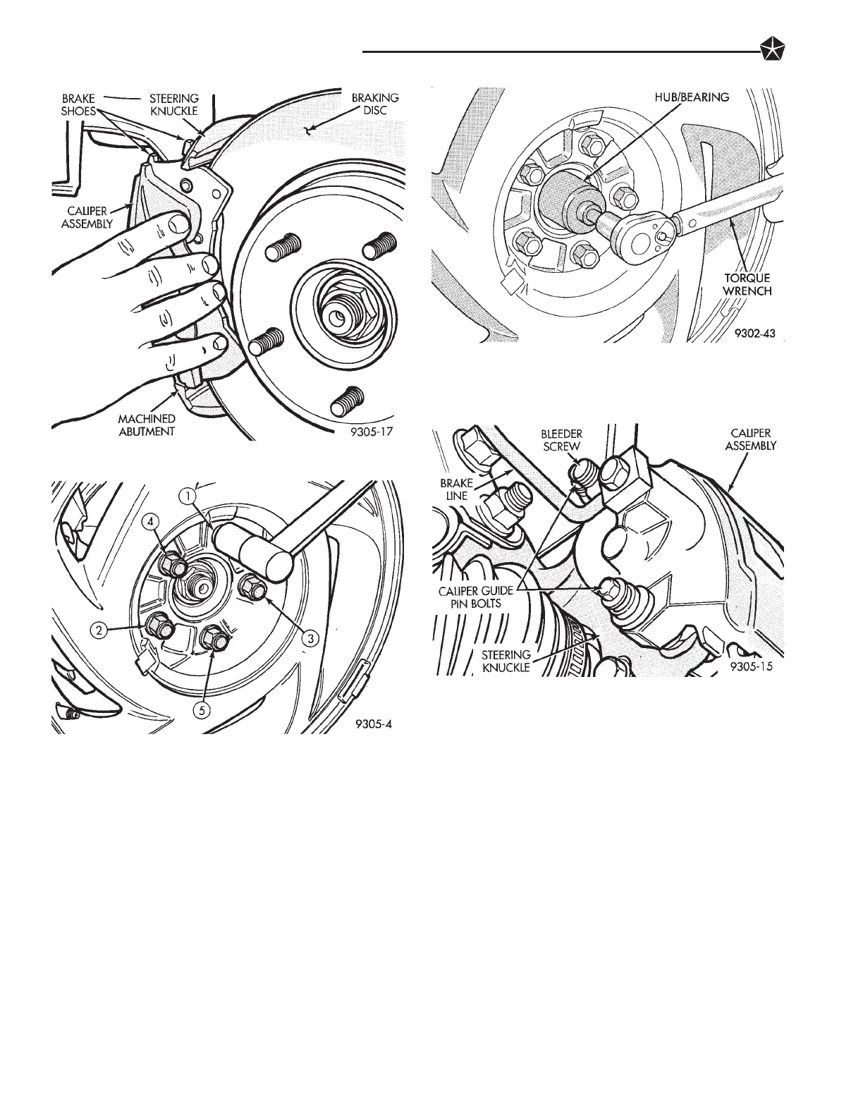
(5) Remove the hub and bearing to stub axle re-
taining nut (Fig. 3).
(6) Remove the 3 steering knuckle to hub and
bearing assembly attaching bolts (Fig. 4).
CAUTION: If metal seal (Fig. 5) on hub and bearing
assembly is seized to steering knuckle and be-
comes dislodged on hub and bearing assembly dur-
ing bearing removal. The hub and bearing assembly
MUST not be reused and MUST be replaced with a
new hub and bearing assembly.
CAUTION: When removing hub and bearing assem-
bly from steering knuckle, be careful not to damage
the flinger disc (Fig. 5) on hub and bearing assem-
bly. If flinger disc becomes damaged, hub and bear-
ing assembly MUST not be used and MUST be
replaced with a new hub and bearing assembly.
Fig. 18 Disc Brake Caliper Mounting
Fig. 19 Tightening Wheel Nuts
Fig. 20 Tighten Hub And Bearing Retaining Nut
Fig. 1 Disc Brake Caliper Mounting
2 - 34 SUSPENSION AND DRIVESHAFTS
 Loading...