HYDRAULIC CONTROL UNIT FLUID RESERVOIR
(FLS2)
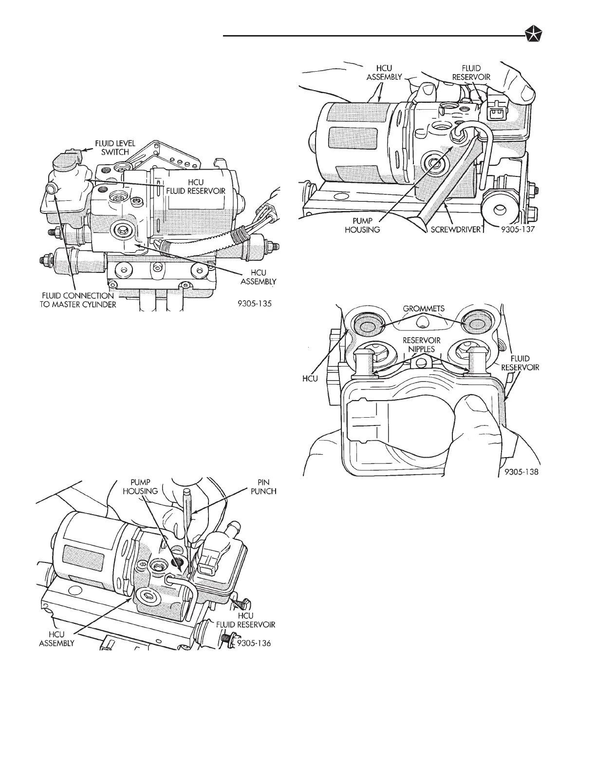
The reservoir at the H.C.U. (Fig. 1) includes the
(FLS2) fluid level switch. This reservoir is connected
to the master cylinder reservoir by a low pressure
hydraulic tube.
REMOVE
(1) Remove the (HCU) assembly from the vehicle.
Refer to Hydraulic Control Unit Removal, in this sec-
tion of the service manual for the required removal
procedure.
(2) Drain brake fluid from (HCU) fluid reservoir.
(3) Using a 1/8 in. pin punch, drive (HCU) fluid
reservoir retaining roll pin down until it is below
hole in fluid reservoir (Fig. 2). Note: If replacing res-
ervoir on a (HCU) with traction control, drive pin
completely out of pump housing.
(4) Insert a screwdriver between pump housing
and reservoir (Fig. 3). Carefully pry fluid reservoir
off of (HCU) assembly.
INSTALL
(1) Lubricate the (HCU) grommets and reservoir
nipples with fresh clean brake fluid (Fig. 4).
(2) Place reservoir nipples against grommets. Rock
reservoir up and down while pushing on reservoir
until reservoir is fully seated into grommets. Reser-
voir is fully installed, when hole in reservoir is in
line with retaining pin hole in pump housing.
(3) From bottom side of (HCU), drive reservoir re-
taining pin up until it extends up above retaining
hole in fluid reservoir (Fig. 5).
Note: If the (HCU) reservoir being replaced is on a
(HCU) for a vehicle equipped with traction control.
Reservoir retaining will have to be replaced from the
top.
(4) Install (HCU) assembly back in the vehicle. Re-
fer to Hydraulic Control Unit Installation, in this
section of the service manual for the required instal-
lation procedure.
(5) Bleed the air from brake hydraulic system. Re-
fer to Bleeding Teves Mark IV Anti-Lock Brake Sys-
tem in this section of the manual for proper bleeding
Fig. 1 HCU Fluid Reservoir And Fluid Level Switch
Fig. 2 Removing (HCU) Reservoir Retaining pin
Fig. 3 Remove Fluid Reservoir From (HCU)
Fig. 4 Installing (HCU) Fluid Reservoir
5 - 96 ANTI-LOCK BRAKE SYSTEM