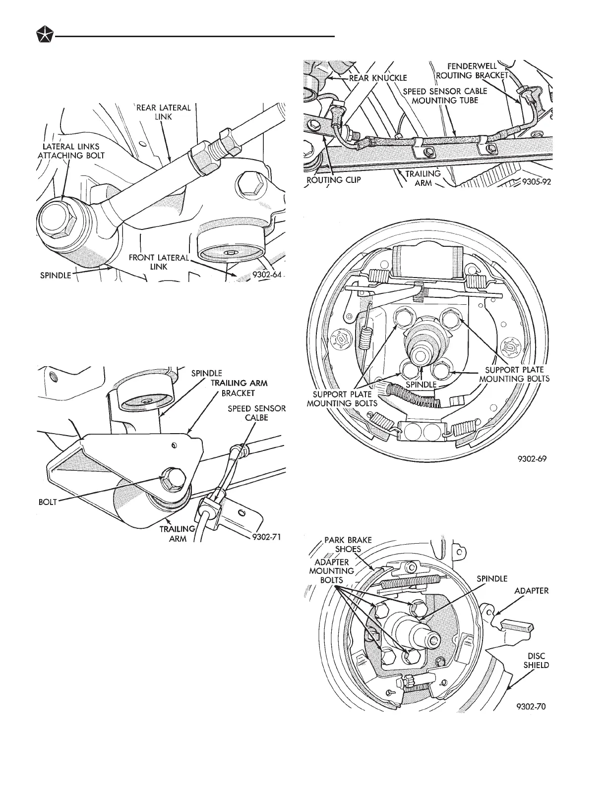
(2) Install the lateral links to spindle attaching
bolt (Fig. 14). Torque the lateral links to spindle at-
taching bolt to 140 NIm (105 ft. lbs.).
(3) Install bolt attaching trailing arm to trailing
arm bracket on bottom of spindle (Fig. 15). Torque
trailing arm to trailing arm bracket attaching bolt to
100 NIm (74 ft. lbs.).
(4) If vehicle is equipped with Anti-Lock Brakes.
Mount rear speed sensor cable routing tube to the
rear trailing arm and speed sensor cable routing
bracket to trailing arm bracket at rear spindle (Fig.
16).
(5) On vehicles equipped with rear drum brakes.
Install the rear brake support plate onto the spindle
(Fig. 17). Install the 4 bolts attaching the rear brake
support plate to the rear spindle (Fig. 17). Torque the
brake support plate to spindle mounting bolts to 115
NIm (85 ft. lbs.).
(6) On vehicles equipped with rear disc brakes. In-
stall the disc brake adapter back on the spindle (Fig.
18). Install the 4 bolts attaching the disc brake
adapter to the rear spindle (Fig. 18). Torque the disc
brake adapter to spindle mounting bolts to 115 NIm
(85 ft. lbs.).
Fig. 14 Lateral Links To Spindle Attaching Bolt
Fig. 15 Trailing Arm To Spindle Bracket Bolt
Fig. 16 Speed Sensor Routing Tube And Bracket
Fig. 17 Brake Support Plate Mounting Bolts
Fig. 18 Disc Brake Adapter Mounting
SUSPENSION AND DRIVESHAFTS 2 - 63








 To Next Page