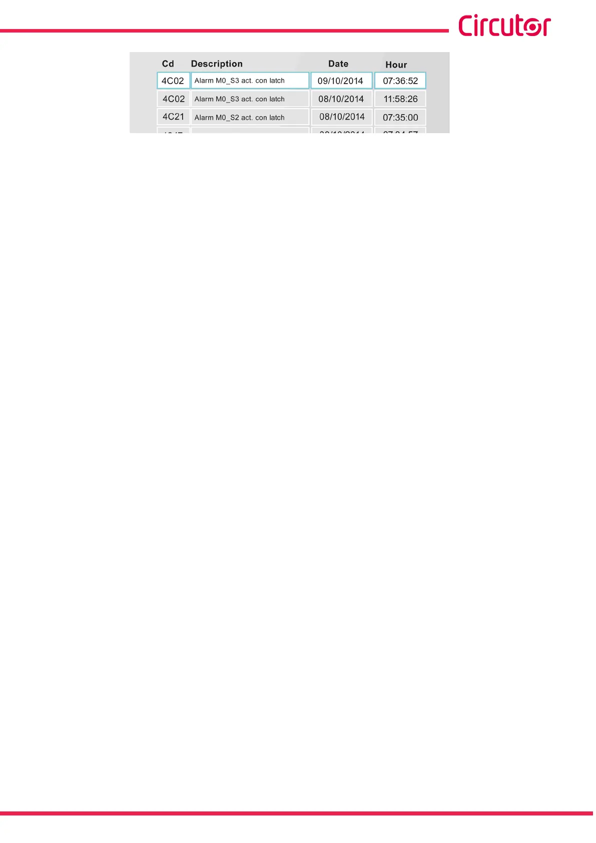
Figure 213: Details of the alarm log�
The alarm log,Figure 213, has 4 columns:
Cd� : Indicates the code of the alarm that occurred (in hexadecimal)
Description: Description of the alarm.
Example: Alarm M0_S3 act with latch
M0, Indicates the module where the alarm was activated:
M0, is an alarm triggered in the device.
M1 ...M4, is an alarm in the expansion module 1...4.
S3, Indicates the module output that has activated the alarm.
In the event of alarms installed in the device, M0:
- S1, is the digital output of transistor 1.
- S2, is the digital output of transistor 2.
- S3, is the digital output of relay 1.
- S4, is the digital output of relay 2.
Date : Date of the alarm.
Hour: Time of the alarm.
The alarm log can be deleted on the Parameter reset screen of the setup menu ( “5.7.20.- PA-
RAMETER RESET.”)
157
Instruction Manual
CVM-A1000 - CVM-A1500