6�3�11�5�2�- Transistor digital outputs
The Latch variable occupies 2 registers.
All other variables occupy 1 register each.
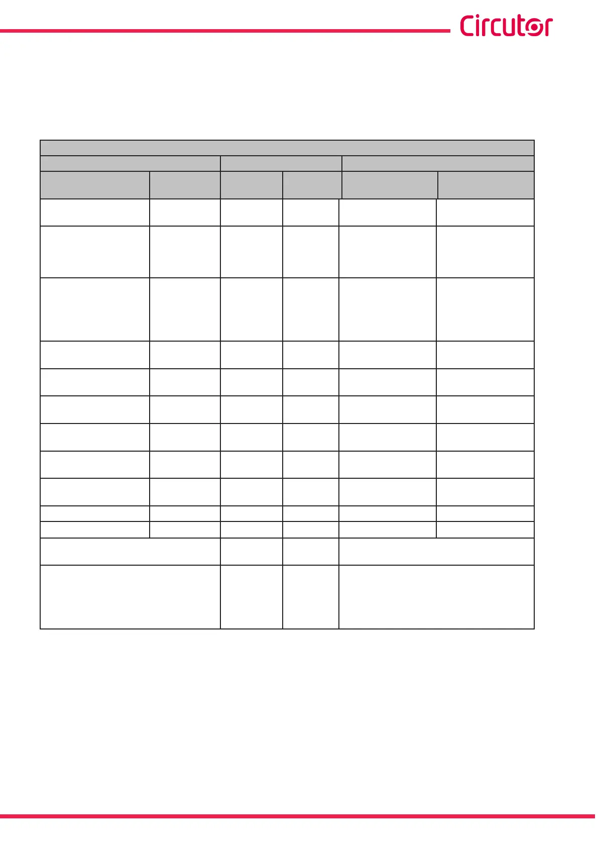
Table 83: Modbus memory map: Alarm status: Transistor digital outputs�
Alarm status: Transistor digital outputs
Configuration variable
Address
Valid data window
Alarm
Impulse
output
Output 1 Output 2
Alarm
Impulse
output
Latch
(72)
kWh or Wh 7530-7531 7544-7545
0: unlock alarm
1: locked alarm
kWh or Wh energy
meter
Delay in the
connection
(73)
Wh or mWh 7532 7546
Energy meter which
indicates the value
of the connection
delay variable (ON)
Wh or mWh energy
meter
Delay in the
disconnection
(73)
Energy meter
factor
7533 7547
Energy meter which
indicates the value
of the disconnec-
tion delay variable
(OFF)
Energy meter factor
meter
Alarm activation date:
Year
(73)
-
7534 7548 2013 to 2076 -
Alarm activation date:
Month
(73)
-
7535 7549 1 to 12 -
Alarm activation date:
Day
(73)
-
7536 754A 1 to 31 -
Alarm activation time:
Hour
(73)
- 7537 754B 0 to 23 -
Alarm activation time:
Minutes
(73)
- 7538 754C 0 to 59 -
Alarm activation time:
Seconds
(73)
- 7539 754D 0 to 59 -
Not used Not used 753A 754E - -
Not used Not used 753B 754F - -
Status
(73)
753C 7550
0: No alarm,
1: Active alarm
Alarm status
(73)
753A 754E
0: No alarm,
1: Pre-alarm,
2: Connection or disconnection delay,
3: Alarm,
4: Impulses,
(72)
If the latch option has been programmed in an alarm and it has been activated, the alarm will be unlocked with
this option.
(73)
For these variables only Function 0x04 is implemented: reading registers.
Note: The 14 registers must be read at once (as a group), otherwise it will respond with an
error.
257
Instruction Manual
CVM-A1000 - CVM-A1500