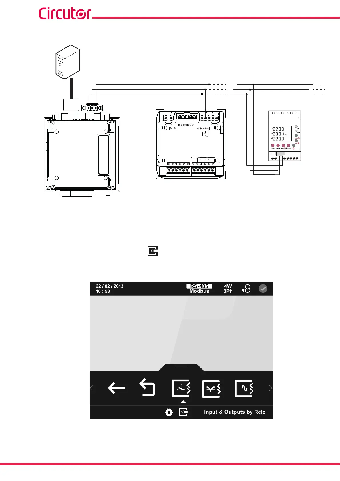
7�5�3�- CONNECTION DIAGRAM
B(-)
A(+)
S
PC
Ethernet
RS-485
POWER SUPPLY
INPUTS
A(+) B(-)
GND
RS485
S1 S2
S1 S2
S1 S2
L1
P1 P2
L2
L3
300V
~
Ph-NPh-Ph
520V
~
NV
L3L2
V
L1
V
P1 P2
P1 P2
I1 I2
OUTPUTS
Rc R2 R1 Tc T2 T1
S0-
S0+ S0+
B(-)
A(+)
S
CVM A-1xxx
+
M-CVM-AB-Modbus
TCP (Bridge)
CVM C10
CVM MINI
Figure 367:Modbus TCP (Bridge) connection diagram�
7�5�4�- CONFIGURATION
Access the conguration menu, as described in “5.7.- SETUP MENU”, and enter the congura-
tion icon of the expansion modules, .
The main screen of the expansion modules is shown in Figure 368.
Figure 368: Main screen of expansion modules�
Displayed here are all the expansion modules connected to the device.
308
CVM-A1000 - CVM-A1500
Instruction Manual