7.7.- PROFIBUS COMMUNICATIONS MODULE
The Probus communications module, M-CVM-AB-Probus, enables communicating the
CVM-A with a Probus network.
7�7�1�- CONNECTION TERMINALS
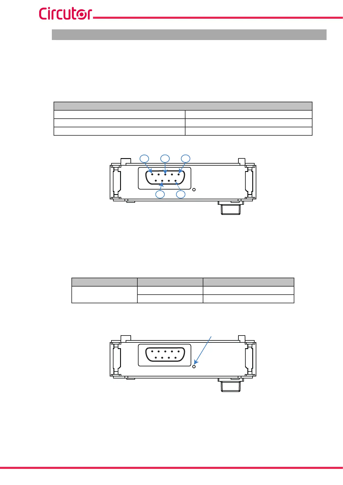
Table 153: List of terminals, Probus communications module.
Connection terminals
1: Shield 6: P5, 5V supply voltage
3: B, No inverting input/output signal from Probus 8: A, Inverting input/output signal from Probus
5: M5 GND, Data reference potencial
1
6
3
8
5
Figure 383: Probus communications module terminals.
7�7�2�- LEDs
Table 154: List of LEDs, Probus communications module.
LED State Function
BUS ERROR
ON Communications error
OFF Work correctly
BUS ERROR
Figure 384: Probus LED.
326
CVM-A1000 - CVM-A1500
Instruction Manual