Table 18:Incremental parameters (display 1 parameter)�
Icon
Display 1 parameter
Incremental parameters
Active energy
(7)(8)(9)
Inductive reactive energy
(7)(8)(9)
Capacitive reactive energy
(7)(8)(9)
Total reactive energy
(7)(8)(9)
Apparent energy
(7)(8)(9)
Active tariff hours
CO
2
Emissions
Cost
(7)
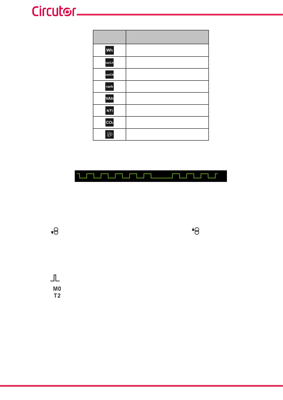
There is a graphical representation for all these parameters on the screen, Figure 35, which
indicates the energy increase: a at line indicates that there is no energy increase and the puls-
es indicate an increase in it.
Figure 57: Graphical representation of the energy increase�
Note: This representation is not real, it is only signicant to give the user an idea of the energy
increase.
(8)
The following icons appear for all these parameters on the screen:
Indicating that the parameter refers to consumed or generated energy.
If the 2 icons light up at the same time, it means the installation is not properly connected.
(9)
The value of the energy parameters is saved in the non-volatile memory every minute.
If there is a transistor digital output or input, programmed in impulse mode, associated with the
variable being displayed, the following will appear:
The icon that indicates that an impulse input or output has been programmed
The module with which the alarm is associated.
The associated output in the module.
66
CVM-A1000 - CVM-A1500
Instruction Manual