1-5
Hardware Installation Guide for the Cisco 4000 Series Integrated Services Router
OL-32185-02
Chapter 1 Overview of Cisco 4000 Series ISRs
Chassis Views
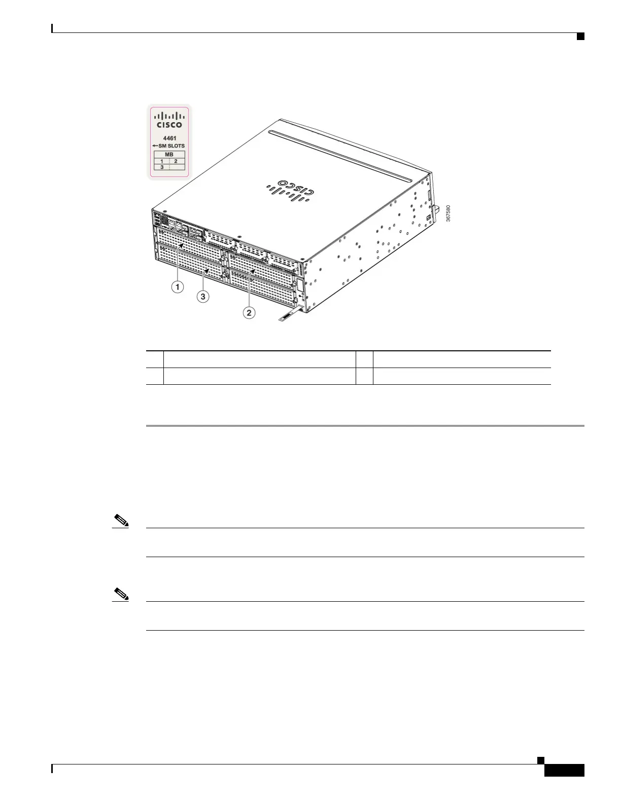
Figure 1-3 NIM and SM-X Slots
To remove an SM-X:
Step 1 Read the “Safety Warnings” section and disconnect the power supply before you replace any module.
Step 2 Access the SM-X slot. See Figure 1-3 for the various NIM and SM-X slot locations.
Step 3 Loosen the captive screws to open the slot cover.
Step 4 Pull the SM-X out of the connector on the motherboard. Keep the SM-X parallel with the motherboard
to prevent damage to the slot and standoff.
Note When you remove the SM-X slot 2, it removes the blank slot which is attached to the special divider.
See Figure 1-4.
Step 5 Place the SM-X in an anti-static bag to protect it from ESD damage.
Note For more details on installation of SM-Xs, NIMs, and Cisco E-Series Server Modules, see the hardware
installation guide for the particular module you have purchased.
1 SM-X slot 1 2 SM-X slot 2
3 SM-X slot 3

 Loading...


