4-3
Cisco ASR 1000 Series Aggregation Services Routers Hardware Installation Guide
OL-13208-11
Chapter 4 Cisco ASR 1000 Series Router SPA Interface Processors (SIPs)
Cisco ASR 1000 Series SPA Interface Processor
This section describes the Cisco ASR 1000 Series SPA Interface (SIP) components and subslot
identification.Figure 4-1 shows an example of the Cisco ASR 1000 Series SPA Interface (SIP) module.
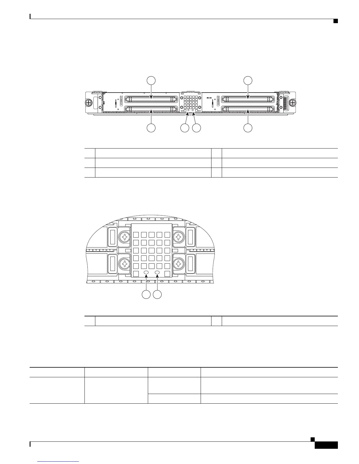
Figure 4-1 Cisco ASR 1000 Series SPA Interface Processor Bay Numbering
Figure 4-2 shows the LEDs on the Cisco ASR1000-SIP10.
Figure 4-2 Cisco ASR1000-SIP10 SPA Interface Processor
Table 4-1 describes the Cisco ASR1000-SIP10 and Cisco ASR1000-SIP40 LEDs on the front panel.
2
0
3
1
231510
ASR1000-SIP10
PWR STATUS
ASR1000-SIP10G
1 2
3
546
1 SPA subslot 0 4 STATUS Led
2 SPA subslot 1 5 PWR Led
3 SPA subslot 2 6 SPA subslot 3
1 STATUS LED 2 PWR LED
280081
12
Table 4-1 Cisco ASR1000-SIP LEDs
LED Label LED Color Behavior Description
PWR Power Solid green Cisco ASR 1000 Series SIP is powered on and all
power supplies are within their tolerances
Off Cisco ASR 1000 Series SIP is powered off

 Loading...


