8-31
Cisco ASR 1000 Series Aggregation Services Routers Hardware Installation Guide
OL-13208-11
Chapter 8 Cisco ASR 1002 Router Overview and Installation
Connecting the Console and Auxiliary Port Cables
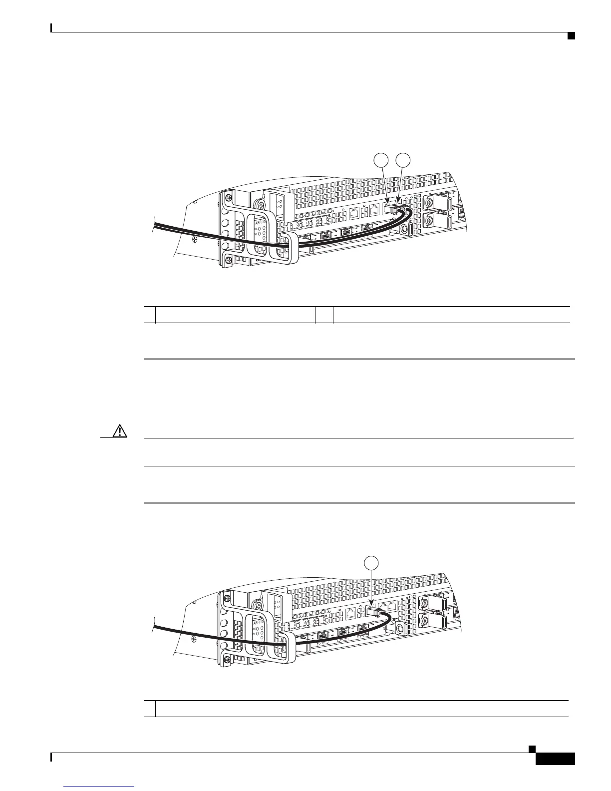
Figure 8-20 shows the Cisco ASR 1002 Router embedded ASR1000-RP1 console and auxiliary port
connectors.
Figure 8-20 Cisco ASR 1002 Router Embedded ASR1000-RP1 Console and Auxiliary Port
Connectors
Step 3
After you establish normal router operation, you can disconnect the terminal.
Management Ethernet Port Cable Connection
Caution To comply with Class A emissions requirements, a shielded Ethernet cable must be used for the
connection.
To use the Management Ethernet interface on the router, perform the following steps:
Step 1 Insert an Ethernet RJ-45 cable into the MGMT ETHERNET port (see Figure 8-21).
Figure 8-21 Cisco ASR 1002 Router Embedded ASR1000-RP1 Management Port Connector
280285
ASR 1002
stat
pwr
min
maj
crit
0
1
C
/
A
A
/
L
0
1
C/
A
A/
L
S
TAT
QE0
Q
E
1
Q
E
2
Q
E3
B
O
O
T
CA
R
RI
E
RLI
N
K
P
WR ST
A
TM
T
S
M
GMT
AU
X
CO
N
S
P
A
-
4X
O
C
3-
P
O
S
S
T
AT
U
S
0
1
2
3
C
/
A
A
/
L
C
/
A
A
/
L
C/A
A
/
L
C
/
A
A
/
L
1 2
1 CON—console port 2 AUX —auxiliary port
1 MGMT - management port and cable
280286
ASR
1002
s
t
at
pw
r
min
ma
j
c
ri
t
0
1
C
/
A
A
/
L
0
1
C/
A
A/
L
STAT
QE
0
Q
E
1
QE
2
Q
E
3B
OOT
C
A
R
RI
E
RLI
NK
P
WR S
TA
TM
T
S
M
GM
T
A
U
X
C
O
N
S
P
A-
4
XOC
3-P
O
S
S
T
AT
U
S
0
1
2
3
C
/
A
A
/
L
C
/
A
A
/
L
C/A
A
/
L
C
/
A
A
/
L
1

 Loading...


