6-22
Cisco ASR 1000 Series Aggregation Services Routers Hardware Installation Guide
OL-13208-11
Chapter 6 Cisco ASR 1006 Router Overview and Installation
Connecting the Console and Auxiliary Port Cables
Shared port adapter documents are also available on the Cisco Documentation DVD.
Connecting the Console and Auxiliary Port Cables
The Cisco ASR 1006 Router has a DCE-mode console port for connecting a console terminal and an
auxiliary port for additional connections to your chassis. The auxiliary port can also be used for
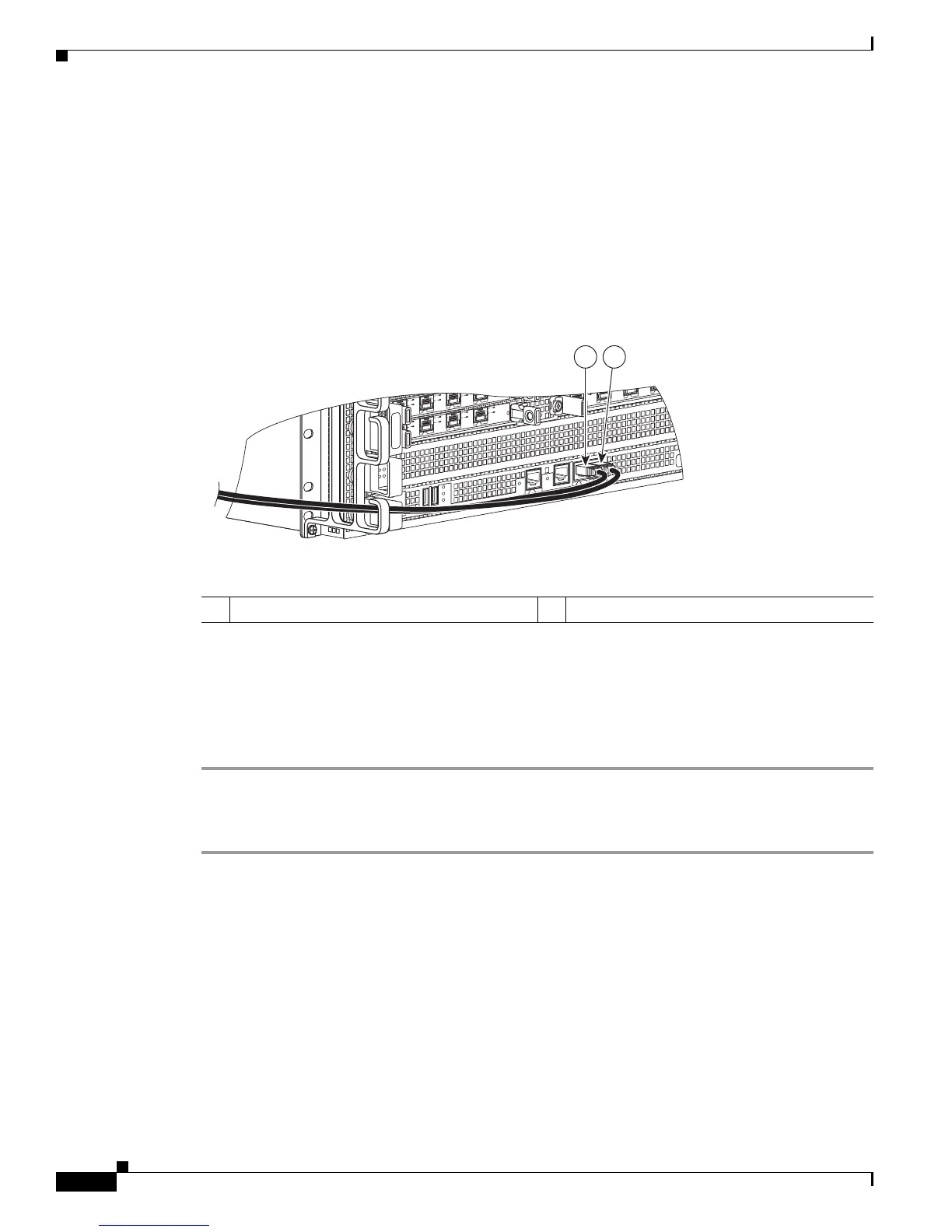
diagnostics. Figure 6-15 shows the CON and AUX ports on the Cisco ASR 1000 Series route processor
card.
Figure 6-15 Cisco ASR 1000 Series Route Processor—CON and AUX Ports
The Cisco ASR 1006 Router uses RJ-45 ports for both the auxiliary port and the console port. Both the
console and the auxiliary ports are asynchronous serial ports; any devices connected to these ports must
be capable of asynchronous transmission.
For console and auxiliary port pinouts for the RJ-45 connector, see Appendix A, “Cisco ASR 1006
Router Specifications.” Both ports are configured as asynchronous serial ports.
Step 1 Before connecting a terminal to the console port, configure the terminal to match the chassis console
port as follows: 9600 baud, 8 data bits, no parity, 1 stop bits (9600 8N1).
Step 2 After you establish normal router operation, you can disconnect the terminal.
Connecting the Ethernet Management Port Cable
When using the Fast Ethernet Management port in the default mode (speed-auto and duplex-auto) the
port operates in auto-MDI/MDI-X mode. The port automatically provides the correct signal connectivity
through the Auto-MDI/MDI-X feature. The port automatically senses a crossover or straight-through
cable and adapts to it.
However, when the Fast Ethernet Management port is configured to a fixed speed (10 or 100 Mbps)
through command-line interface (CLI) commands, the port is forced to MDI mode.
When in a fixed-speed configuration and MDI mode:
MI
N
A
C
O
MA
J
STB
Y
A
C
T
V
S
TA
T
ASR100
0-R
P
1
P
WR
C
R
I
T
0
SPA
-
4
X
O
C3
-
POS
0
1
2
3
A
A
/
L
C/A
A
/L
C/A
A/L
SPA
-4
X
O
C
3
-P
O
S
S
TATU
S
0
1
2
3
C/
A
A
/L
C/A
A
/
L
C/A
A
/
L
C/A
A
/L
S
PA
-
4
X
O
C
3
-P
O
S
S
T
AT
US
0
1
2
3
C/
A
A
/L
C/A
A
/
L
C/A
A
/
L
C
/
A
A/L
B
I
T
S
C
O
N
A
UX
CA
RR
IER
LIN
K
M
GMT
ET
H
E
R
N
E
T
DISK
HD
USB
DF
0
1
1 CON connector 2 AUX connector

 Loading...


