6-3
Cisco ASR 1000 Series Aggregation Services Routers Hardware Installation Guide
OL-13208-11
Chapter 6 Cisco ASR 1006 Router Overview and Installation
Cisco ASR 1006 Router Description
Rear View
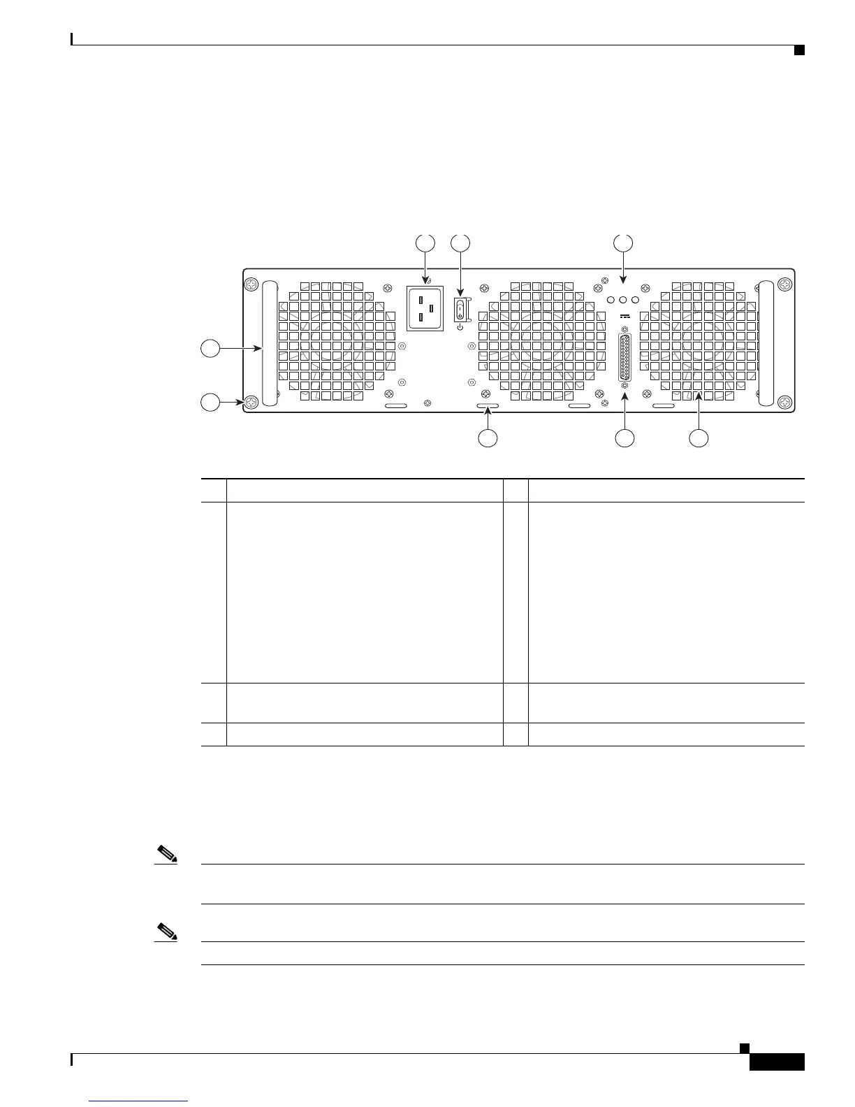
Figure 6-2 shows the rear of the Cisco ASR 1006 Router with the ASR1006-PWR-AC power supply
installed.
Figure 6-2 Cisco ASR 1006 Router Rear View with the AC Power Supply (ASR1006-PWR-AC)
Internal fans draw cooling air into the chassis and across internal components to maintain an acceptable
operating temperature. (See Figure 6-2.) The fans are located at the rear of the chassis. A two-hole
grounding lug is located on the side of the chassis. Two power supplies, either two AC power supplies
or two DC power supplies, are accessed from the rear of the router.
Note You have already unpacked your chassis and read all the site requirements for your new equipment.
Proceed with the installation.
Note Do not combine AC and DC power supplies in the same chassis.
1 AC power supply fan 5 AC power supply handle
2 AC power supply DB-25 alarm connector—A
female DB-25 sub connector which enables
you to attach an external alarm monitoring
facility to the router, thus supporting a
telco-style of handling alarm conditions in the
router.
For a description of the DB-25 alarm
connector, see the “How Cisco ASR1000-RP
Alarm Monitoring Works” section on
page 2-20.
6 AC power inlet
3 Cable tie wrap tabs 7 AC power supply Standby switch. A Standby
switch is not considered a disconnect.
4 AC power supply captive screws 8 AC power supply LEDs
280029
OUTPUT INPUT INPUT
FAIL OK OK
ALARMS
60V
1A MAX
100-240V~ 16-7A
50-60HZ
This unit might have more than
one power supply connection.
All connections must be removed
to de-energize the unit.
2 13
4
5
6 7
8

 Loading...


