7-31
Cisco ASR 1000 Series Aggregation Services Routers Hardware Installation Guide
OL-13208-11
Chapter 7 Cisco ASR 1004 Router Overview and Installation
Connecting the Network Management and Signal System Cables
Step 1 Connect one end of the RJ-45 cables to the serial RJ-45 port (CON) on the Cisco ASR 1000 Series Route
Processor 1 (see Figure 7-21).
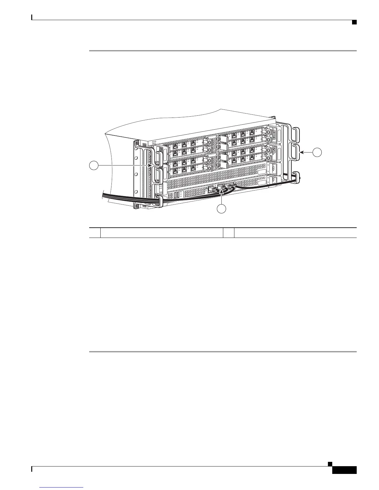
Step 2 Run the cable up and through the cable-management bracket and connect the other end of the RJ-45
cable to the RJ-45 adapter (see Figure 7-22).
Figure 7-22 Cisco ASR 1004 Router Cable-Management Bracket
Step 3
Connect the adapter to your video terminal to complete the cable connection.
Step 4 Power on your video terminal.
Step 5 Configure your video terminal to match the following default console port settings:
• 9600 baud
• 8 data bits
• No parity generation or checking
• 1 stop bit
• No flow control
Step 6 Go to the “Connecting the Network Management and Signal System Cables” section on page 7-31 to
continue the installation.
Connecting the Network Management and Signal System
Cables
The Cisco ASR 1004 Router has connections to both the internal Ethernet management network and the
external data network.
• The internal Ethernet management network connections are made through an Ethernet port on the
front panel of the Cisco ASR 1000 Series Route Processor 1.
1 BITS port connection 2 Cable-management bracket U feature device
MI
N
A
C
O
MA
J
STB
Y
A
CT
V
S
T
AT
ASR1
00
0-RP1
PWR
CRIT
280183
SP
A
-
4
X
O
C
3
-P
O
S
S
TAT
U
S
0
1
2
3
C/
A
A
/L
C/A
A
/L
C/
A
A
/L
C/A
A
/L
S
P
A
-
4
X
O
C
3
-P
O
S
S
T
AT
US
0
1
2
3
C/A
A
/L
C/A
A
/L
C/
A
A
/L
C/A
A
/L
SP
A
-
4
X
O
C
3
-P
O
S
S
TAT
U
S
0
1
2
3
C/A
A
/L
C/A
A
/L
C/
A
A
/L
C/A
A
/
L
SP
A
-
4
X
O
C
3
-
P
O
S
S
T
AT
U
S
0
1
2
3
C/A
A
/
L
C/A
A
/L
C/A
A
/L
C/A
A
/L
SP
A
-
4
X
O
C
3
-
P
O
S
S
TA
T
US
0
1
2
3
C/A
A
/L
C/
A
A
/L
C/A
A
/L
C/A
A
/L
SP
A
-
4
X
O
C
3
-P
O
S
S
T
AT
U
S
0
1
2
3
C/A
A
/L
C/
A
A
/
L
C/A
A
/
L
C/A
A
/
L
SP
A
-
4
X
O
C
3
-
P
O
S
S
TA
TU
S
0
1
2
3
C/
A
A
/L
C/A
A
/L
C/A
A
/L
C/A
A
/L
SP
A
-
4
X
O
C
3
-
P
O
S
S
TAT
U
S
0
1
2
3
C/A
A
/L
C/A
A
/L
C/A
A
/
L
C
/A
A
/L
B
ITS
C
ON
A
U
X
CARRIER
LINK
M
G
M
T
E
THE
R
N
E
T
DISK
HD
USB
DF
0
1
1
2
2

 Loading...


