11-26
Cisco ASR 1000 Series Aggregation Services Routers Hardware Installation Guide
OL-13208-11
Chapter 11 Cisco ASR 1013 Router Overview and Installation
Connecting the Console and Auxiliary Port Cables
http://www.cisco.com/en/US/partner/docs/interfaces_modules/port_adapters/install_upgrade/pos/pa-po
s-oc3_install_config/paposoc3.html
Shared port adapter documents are also available on the Cisco Documentation DVD.
Connecting the Console and Auxiliary Port Cables
The Cisco ASR 1013 Router has a DCE-mode console port for connecting a console terminal and an
auxiliary port for additional connections to your chassis. The auxiliary port can also be used for
diagnostics.
In a fully redundant chassis, each Cisco ASR1000-RP2 is separately connected to each FP and I/O card
slot over separate point-to-point connections of the system interconnect over the midplane. The selection
of the active RP2s is made separately from the selection of the active embedded services processor.
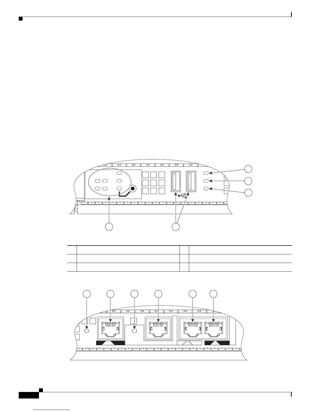
Figure 11-11 and Figure 11-12 show the Cisco ASR 1000 Series Route Processor faceplate.
Figure 11-11 Cisco ASR1000-RP2 Faceplate LEDs
Figure 11-12 Cisco ASR 1000 Series Route Processor Faceplate Connectors
1 Internal hard drive LED 4 USB 0, USB 1 connector
2 External USB Flash LED 5 ASR1000-RP2 LEDs
3 Internal USB bootflash LED — —
01
DISK
BF
USB
HD
MIN
ACO
MAJ
STBY
ACTV
STAT
ASR1000-RP1
PWR
CRIT
280078
5
4
1
2
3
CARRIER
LINK
MGMT ETHERNET
BITS CON AUX

 Loading...


