B-2
Cisco ASR 1000 Series Aggregation Services Routers Hardware Installation Guide
OL-13208-11
Appendix B Cisco ASR 1000 Series Router Route Processor and Embedded Services Processor Signals and Pinouts
Cisco ASR 1000-RP1 Pinout Specifications
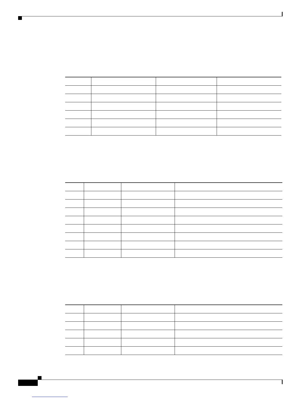
BITS Interface Port Signals and Pinouts
Table B-2 lists the pinouts of the Building Integrated Timing Supply (BITS) RJ45 port.
Console Port Signals and Pinouts
Table B-3 lists the pinouts of the dual RJ-45 ports for the front panel console port.
.
Auxiliary Port Signals and Pinouts
Table B-4 lists the pinouts of the dual RJ-45 ports for the auxiliary port.
Table B-2 BITS RJ-45 Receptacle Pinouts for Cisco ASR1000-RP1
Pin Signal Direction Description
1 RX Ring Input Receive Ring
2 RX TIP Input Receive (T1/E1)
3, 4 N/C — —
5 TX Ring Unused —
6 TX TIP Unused —
7,8 N/C — —
Table B-3 Console Port Pinouts for Cisco ASR1000-RP1
Pin Signal Direction Description
1
RTS Output Request to Send (tied to pin 8, CTS)
2
DTR Output Data Terminal Ready (always On)
3
TXD Output Transmit Data
4
GND — Ring Indicator
5
GND — —
6
RXD Input Receive Data
7
DSR Input unused
8
CTS Input Clear to Send (tied to pin 1, RTS)
Table B-4 Auxiliary Port Pinouts for Cisco ASR1000-RP1
Pin Signal Direction Description
1
RTS Output Request to Send
2
DTR Output Data Terminal Ready (always On)
3
TXD Output Transmit Data
4
RI — Ring Indicator
5
GND — —

 Loading...


