6-26
Cisco ASR 1000 Series Aggregation Services Routers Hardware Installation Guide
OL-13208-11
Chapter 6 Cisco ASR 1006 Router Overview and Installation
Connecting Power to the Cisco ASR 1006 Router
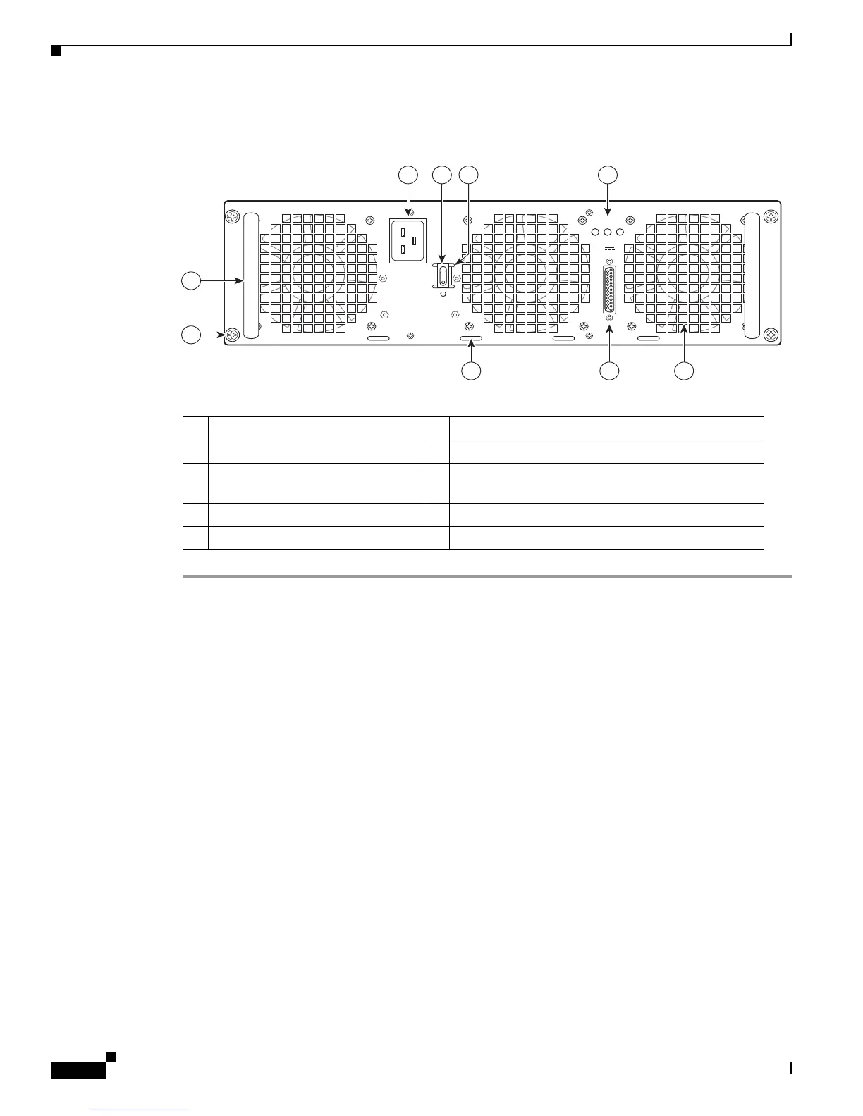
Figure 6-17 shows the ASR1013/06-PWR-AC power supply of the Cisco ASR 1006 Router.
Figure 6-17 Cisco ASR 1006 Router AC Power Supply (ASR1013/06-PWR-AC)
Step 3 Plug the AC power supply cable into the AC power source.
This completes the procedure for connecting AC-input power.
253916
OUTPUT INPUT INPUT
FAIL OK OK
ALARMS
60V
1A MAX
100-240V~ 16-7A
50-60HZ
This unit might have more than
one power supply connection.
All connections must be removed
to de-energize the unit.
2 13
4
5
6 7
9
8
1 AC power supply fan 6 AC power inlet
2 DB-25 alarm connector 7 AC power supply Standby switch
3 Tie-wrap tab 8 Protective shielding on both sides of the Standby
switch
4 AC power supply captive screw 9 AC power supply LEDs
5 AC power supply handle

 Loading...


