8-4
Cisco ASR 1000 Series Aggregation Services Routers Hardware Installation Guide
OL-13208-11
Chapter 8 Cisco ASR 1002 Router Overview and Installation
Cisco ASR 1002 Router Description
Internal fans draw cooling air into the chassis and across internal components to maintain an acceptable
operating temperature. The fans are located at the rear of the chassis. A two-hole grounding lug is located
on the side of the chassis. Two power supplies, either two AC power supplies or two DC power supplies
are accessed from the rear of the router.
Caution Use only AC power supplies or DC power supplies in the Cisco ASR 1002 Router. Do not mix power
supply types.
Cisco ASR 1002 Router Slot Numbering
The Cisco ASR 1002 Router contains one Cisco embedded ASR1002-RP1 which is addressed as R0 and
one Cisco ASR1000-ESP5 or ASR1000-ESP10 forwarding processor in slot F0. The Cisco ASR 1002
Router consists of an embedded ASR1000-RP1 and embedded ASR1000-SIP10 board supporting three
half-height SPAs or 1half-height and one full-height SPA and one Cisco ASR1000-ESP5 forwarding
processor.
The SPA bays are bay 1, bay 2, and bay 3. The built-in 4xGE SPA ports are located in the SPA 0 location
and will be addressed as GE 0/0/x. The Cisco ASR 1002 Router provides a built-in 4-Gigabit Ethernet
interface and this SPA is physically located on the Cisco embedded ASR1000-RP1 board. The Cisco
ASR 1000 Series ESP card is located in slot 1 and labeled as FP0.
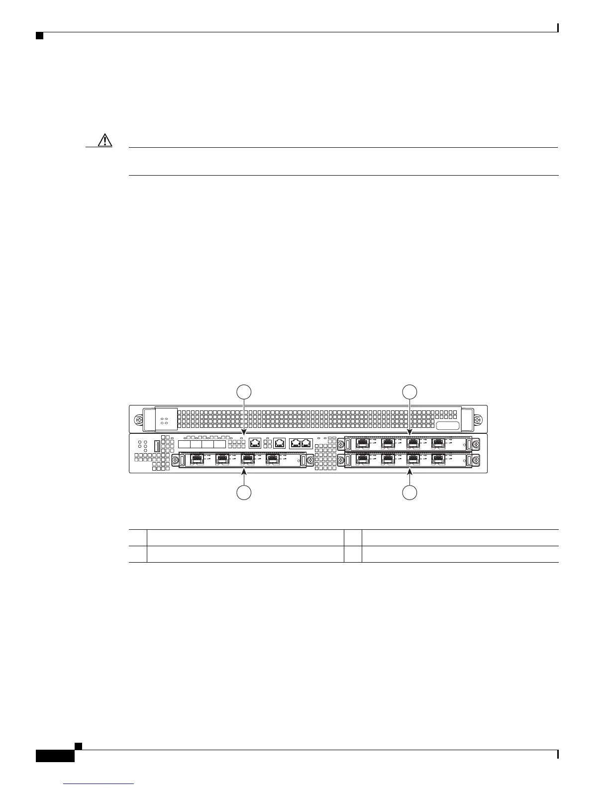
Figure 8-4 shows the Cisco ASR 1002 Router slot numbering.
Figure 8-4 Cisco ASR 1002 Router Slot Numbering
1 Embedded route processor RP0 in subslot 0 3 Cisco SPA subslot 1
2 Cisco SPA subslot 2 4 Cisco SPA subslot 3
ASR 1002
pwr
stat
min
maj
crit
STAT
QE0 QE1 BOOT
C
A
R
R
I
E
R
LINK PWR STATQE2 QE3
SPA-4XOC3-POS
S
T
A
T
U
S
0
1
2
3
C
/A
A
/
L
C
/A
A
/L
C
/
A
A
/L
C
/
A
A
/L
SPA-4XOC3-POS
S
T
AT
US
0
1
2
3
C
/
A
A
/
L
C
/
A
A
/
L
C
/
A
A/
L
C
/
A
A
/
L
SPA-4XOC3-POS
S
T
ATUS
0
1
2
3
C
/
A
A
/
L
C
/
A
A/
L
C/
A
A
/
L
C
/
A
A
/
L
STBY
ACTV
STAT
ASR1000-ESP10
PWR
1
2
3
4
280369

 Loading...


