connecting the optical fiber cables for the PA-POS-OC3 port adapter, see PA-POS-OC3 Port Adapter
Installation and Configuration at the following location:
http://www.cisco.com/en/US/partner/docs/interfaces_modules/port_adapters/install_upgrade/pos/pa-pos-oc3_install_config/paposoc3.html
Connecting the Console and Auxiliary Port Cables
This section describes how to attach a cable to the Cisco embedded ASR1000-RP1 console or auxiliary ports
on the Cisco ASR 1002 Router. The Cisco ASR 1002 Router uses RJ-45 ports for both the auxiliary port and
console port.
To meet Class A emission requirements, shielded cables must be used for the console and auxiliary port
connectors.
Caution
Before you can use the console interface on the router using a terminal or PC, you must perform the following
steps:
SUMMARY STEPS
1.
Before connecting a terminal to the console port, configure the terminal to match the chassis console port
as follows: 9600 baud, 8 data bits, no parity, 1 stop bits (9600 8N1).
2.
Connect to the port using the RJ-45 to DB-9 cable.
3.
After you establish normal router operation, you can disconnect the terminal.
DETAILED STEPS
Step 1
Before connecting a terminal to the console port, configure the terminal to match the chassis console port as follows:
9600 baud, 8 data bits, no parity, 1 stop bits (9600 8N1).
Step 2
Connect to the port using the RJ-45 to DB-9 cable.
For information about how to change the default settings to meet the requirements of your terminal or host, see
Cisco IOS Terminal Services Configuration Guide .
Note
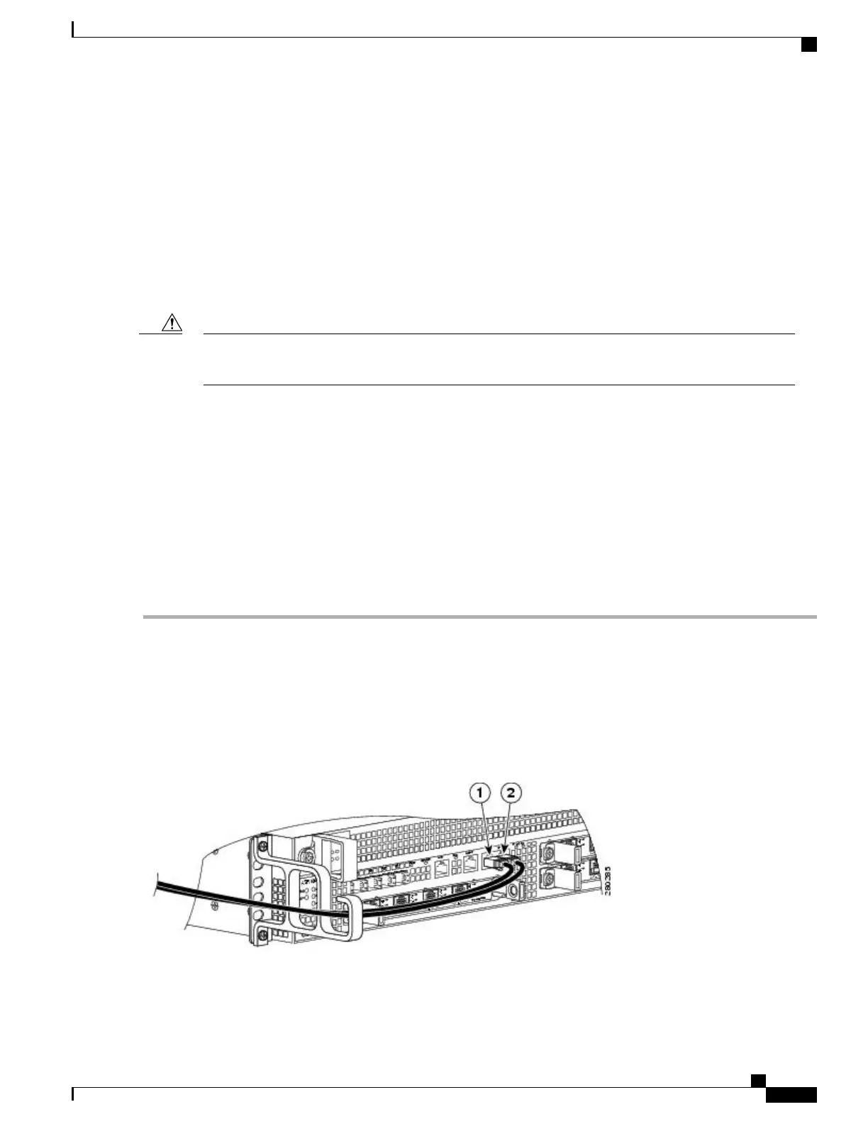
The follwing shows the Cisco ASR 1002 Router embedded ASR1000-RP1 console and auxiliary port connectors.
Figure 98: Cisco ASR 1002 Router Embedded ASR1000-RP1 Console and Auxiliary Port Connectors
Cisco ASR 1000 Series Router Hardware Installation Guide
253
Cisco ASR 1002 Router Overview and Installation
Connecting the Console and Auxiliary Port Cables

 Loading...


