DC power supply slot 1
label
7DC power supply slot 0
label
2
Ground lead8DC power supply switch
Standby/On (|)
3
Positive lead9DC power supply LEDs4
Negative lead10Power supply fan5
Internal fans draw cooling air into the chassis and across internal components to maintain an acceptable
operating temperature. The fans are located at the rear of the chassis. A two-hole grounding lug is located on
the side of the chassis. Two power supplies, either two AC power supplies or two DC power supplies, can be
accessed from the rear of the router.
Use only the AC power supplies or the DC power supplies in the Cisco ASR 1002-X Router. Do not mix
power supply types.
Caution
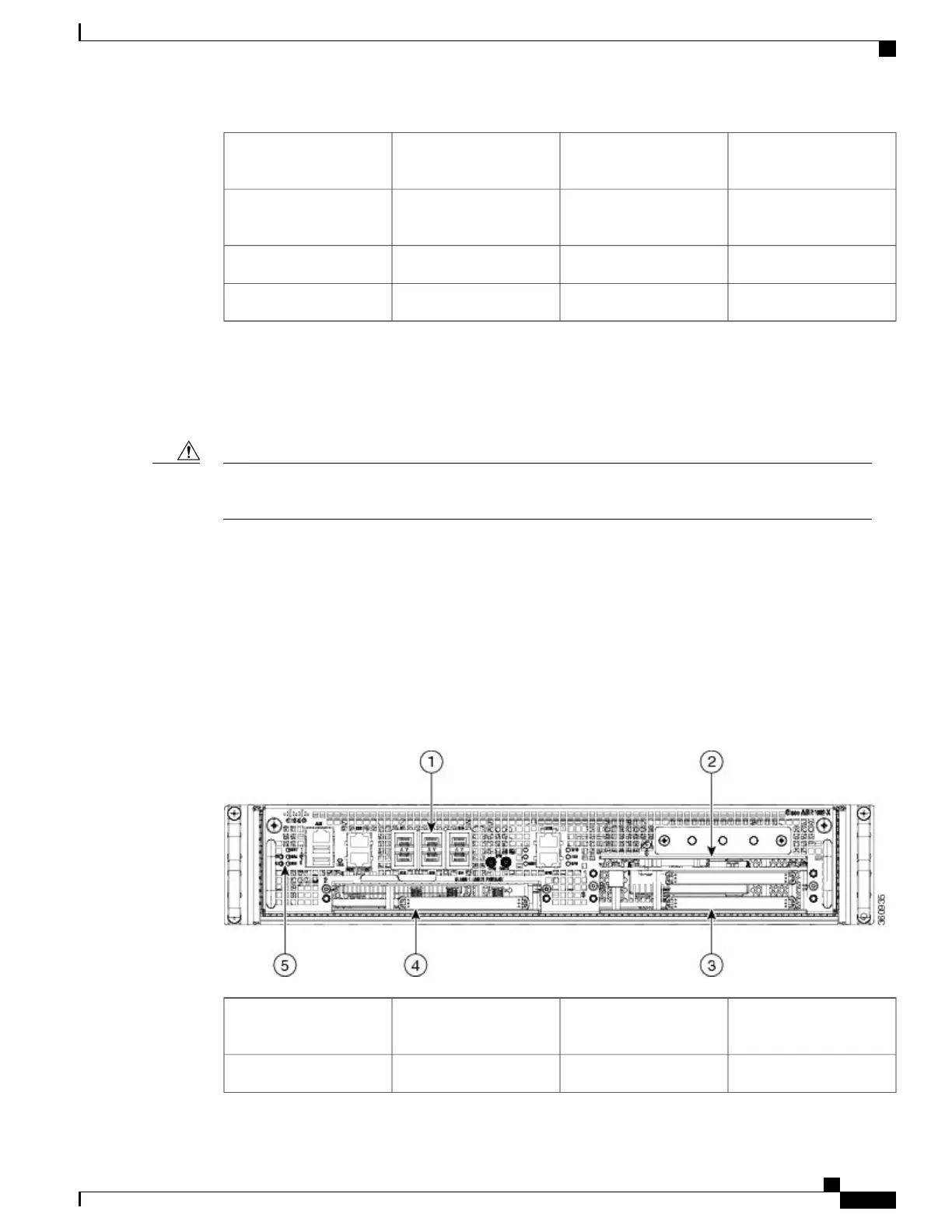
Cisco ASR 1002-X Router Slot Numbering
The Cisco ASR 1002-X Router contains an integrated SIP that supports three half-height SPAs or one
half-height SPA and one full-height SPA. The SPA bays are Bay 1, Bay 2, and Bay 3. The router provides a
built-in 6 Gigabit Ethernet interface, and this SPA is physically located on the integrated route processor
board. The built-in 6xGE SPA ports are located in the SPA Bay 0 and addressed as GE 0/0/x.
The following image shows the Cisco ASR 1002-X Router slot numbering.
Figure 147: Cisco ASR 1002-X Router Slot Numbering
SPA slot 24Built-in 6x1GE SPA in
slot 0
1
ESP LEDs5SPA slot 12
Cisco ASR 1000 Series Router Hardware Installation Guide
321
Cisco ASR 1002-X Router Overview and Installation
Rear View of the Cisco ASR 1002-X Router

 Loading...


