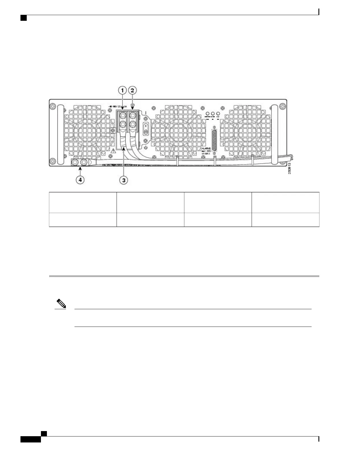
The following figure shows the DC power supply terminal block with cables connected.
Figure 298: Cisco ASR 1013 Router DC Power Supply Terminal Block Cable Connections
Protective sleeving around
the stud and cable
3Negative lead1
Ground stud and cable4Positive lead2
Step 11
Replace the terminal block plastic cover, which is slotted and keyed to fit correctly over the terminal block; then tighten
the black screw (use the screwdriver to tighten the screw to a torque of 5 in-lbs / 1 per.).
Step 12
Remove the tape from the circuit-breaker On/Off switch (if there was any).
Step 13
Switch the circuit breaker On/Off switch to the On (|) position.
What to Do Next
The requirement for maximum torque applied to the power or ground Kepnuts must be 8 in-lb when the
power or ground lug is not present.
Note
This completes the procedure for installing the DC power supply into the Cisco ASR 1013 Router.
Removing and Replacing the Cisco ASR 1001 Router Power
Supplies
The Cisco ASR 1001 Router AC and DC power supplies are shipped installed in the chassis. You must connect
the power supplies when they arrive.
Cisco ASR 1000 Series Router Hardware Installation Guide
598
Removing and Replacing FRUs from the Cisco ASR 1000 Series Routers
Removing and Replacing the Cisco ASR 1001 Router Power Supplies

 Loading...


