Chapter 3 Switch Installation
Installing the Switch
3-34
Catalyst 3750 Switch Hardware Installation Guide
78-15136-03
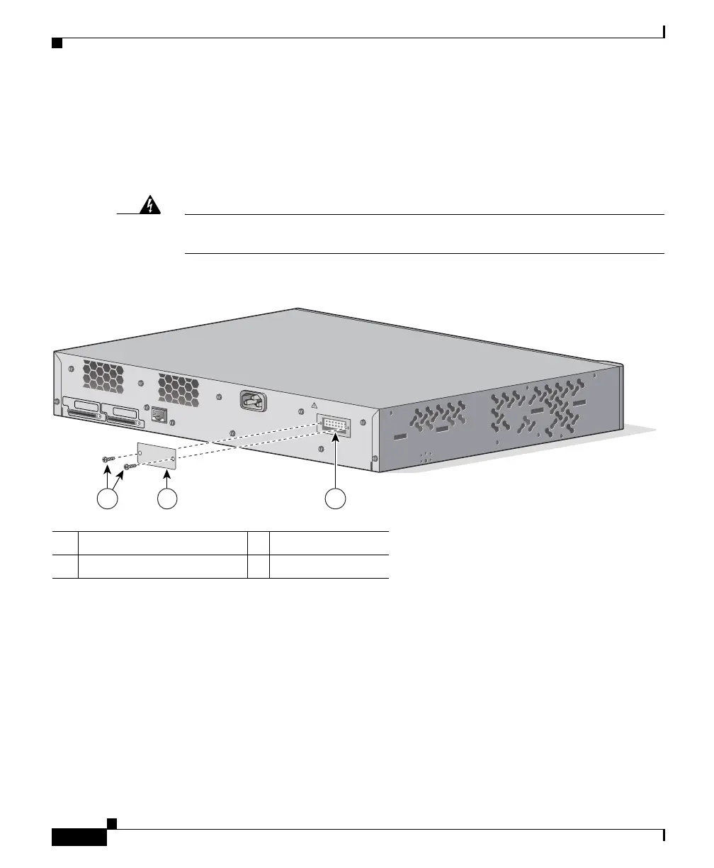
Attaching the RPS Connector Cover
If you are not using an RPS with your switch, use the two Phillips pan-head
screws to attach the RPS connector cover to the back of the switch, as shown in
Figure 3-31 and Figure 3-32.
Warning
If an RPS is not connected to the switch, install an RPS connector cover on the
back of the switch.
Figure 3-31 Attaching the RPS Connector Cover on the Catalyst 3750G-24TS Switch
1 Phillips pan-head screws 3 RPS connector
2 RPS connector cover
CONSOLE
STACK 1
STACK 2
DC INPUTS FO
R REMOTE
PO
W
ER
SUPPLY
SPECIFIED IN MANUAL
+12v @
8.5a
21 3
86571