Chapter 3 Switch Installation
Preparing for Installation
3-8
Catalyst 3750 Switch Hardware Installation Guide
78-15136-03
• Refer to the Catalyst 3750 release notes for cable stipulations for XENPAK
module connections. Each port must match the wave-length specifications on
the other end of the cable, and for reliable communications, the cable must
not exceed the stipulated cable length.
• Operating environment is within the ranges listed in Appendix A, “Technical
Specifications.”
• Clearance to front and rear panels is such that
–
Front-panel indicators can be easily read.
–
Access to ports is sufficient for unrestricted cabling.
Make sure that there is access to the rear of the rack if you are planning
to stack the switches. If you do not have access to the rear panel, make
sure you cable the switches before you rack mount them.
–
Rear-panel power connector is within reach of an AC power receptacle.
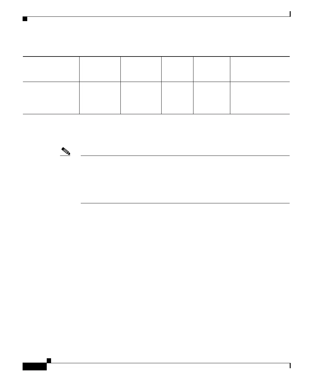
CWDM 1470, 1490,
1510, 1530,
1550, 1570,
1590, 1610
SMF 9/125 — 62 miles (100 km)
1. A mode-conditioning patch cord is required. Using an ordinary patch cord with MMF, 1000BASE-LX/LH SFP modules, and
a short link distance can cause transceiver saturation, resulting in an elevated bit error rate (BER). When using the LX/LH
SFP module with 62.5-micron diameter MMF, you must also install a mode-conditioning patch cord between the SFP module
and the MMF cable on both the sending and receiving ends of the link. The mode-conditioning patch cord is required for link
distances greater than 984 feet (300 m).
Note When using shorter distances of single-mode fiber cable, you might need to insert
an inline optical attenuator in the link to avoid overloading the receiver.
When the fiber-optic cable span is less than15.43 miles (25 km), at each end of
the link, insert a 5-decibel (dB) or 10-dB inline optical attenuator between the
fiber-optic cable plant and the receiving port on the 1000BASE-ZX SFP module.
Table 3-1 Fiber-Optic SFP Module Port Cabling Specifications (continued)
SFP Module
Wavelength
(nanometers) Fiber Type
Core Size
(micron)
Modal
Bandwidth
(MHz/km) Cable Distance