7-3
Catalyst 6500 Series Content Switching Module Configuration Note
OL-4612-01
Chapter 7 Configuring Redundant Connections
Configuring Fault Tolerance
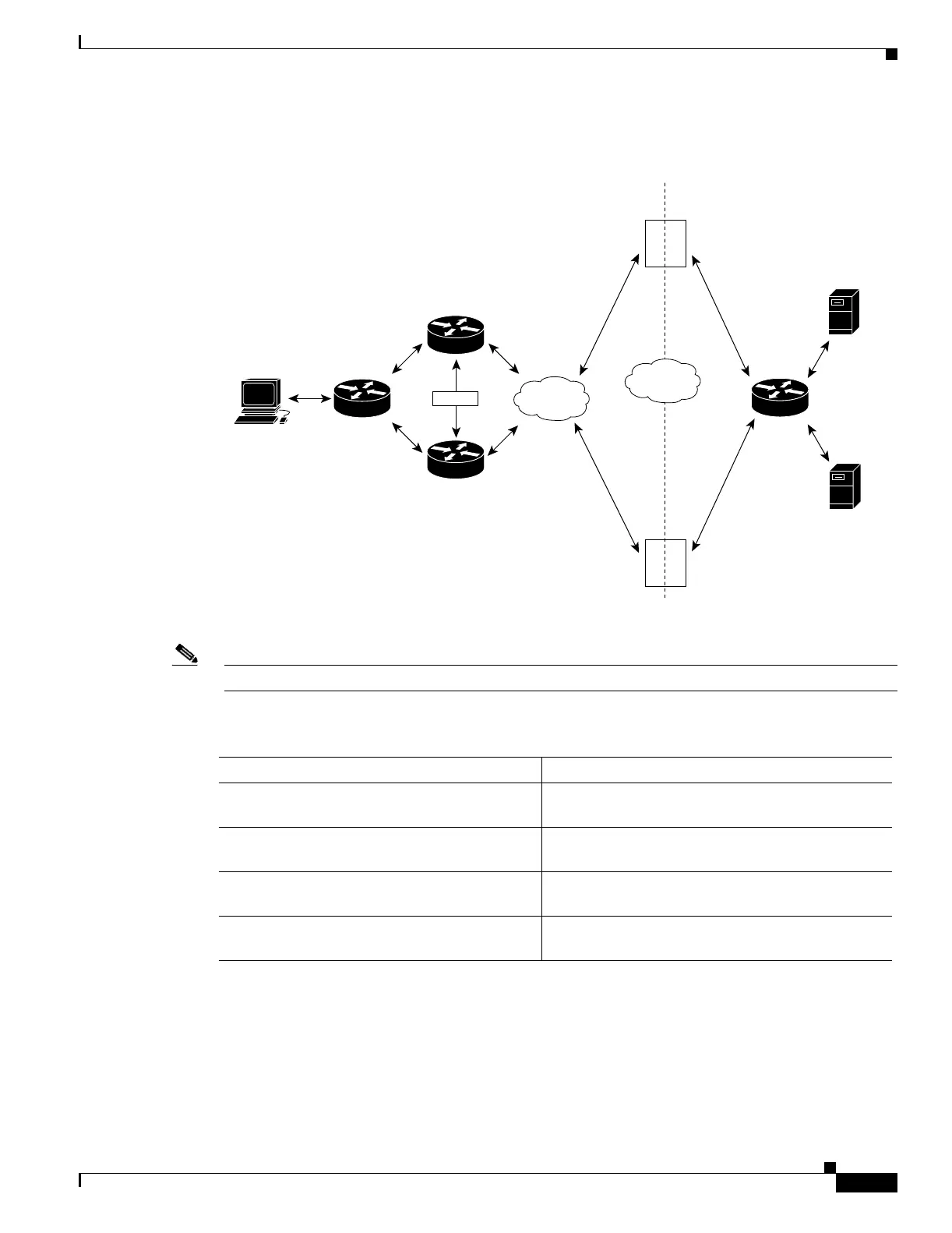
Figure 7-1 Fault-Tolerant Configuration
Note The addresses in Figure 7-1 refer to the steps in the following two task tables.
To configure the active (A) CSM for fault tolerance, perform this task:
VLAN 2
Router A
NAS
router
Client
workstation
Router B
Client-side Server-side
Gateway
192.158.38.20
Gateway
192.158.38.20
HSRP
192.158.38.10
192.158.38.40
192.158.39.10
192.158.39.30
Virtual server 1
Virtual server 1
Alias IP adress
(default gateway)
192.158.39.20
Alias IP adress
(default gateway)
192.158.39.20
IP
address
120181
VLAN 9
Server A
Server B
A
B
Content Switching Module
Content Switching Module
Command Purpose
Step 1
Router(config-module-csm)# vlan 2 client
Creates the client-side VLAN 2 and enters the SLB
VLAN mode
1
.
Step 2
Router(config-slb-vlan-client)# ip addr
192.158.38.10 255.255.255.0
Assigns the content switching IP address on
VLAN 2.
Step 3
Router(config-slb-vlan-client)# gateway
192.158.38.20
(Optional) Defines the client-side VLAN gateway
for an HSRP-enabled gateway.
Step 4
Router(config-module-csm)# vserver vip1
Creates a virtual server and enters the SLB vserver
mode.
 Loading...


