32-29
Cisco IE 3000 Switch Software Configuration Guide
OL-13018-01
Chapter 32 Configuring QoS
Configuring Standard QoS
Table 32-10 shows the default CoS output queue threshold map when QoS is enabled.
Table 32-11 shows the default DSCP output queue threshold map when QoS is enabled.
Default Mapping Table Configuration
The default CoS-to-DSCP map is shown in Table 32-12 on page 32-50.
The default IP-precedence-to-DSCP map is shown in Table 32-13 on page 32-51.
The default DSCP-to-CoS map is shown in Table 32-14 on page 32-53.
The default DSCP-to-DSCP-mutation map is a null map, which maps an incoming DSCP value to the
same DSCP value.
The default policed-DSCP map is a null map, which maps an incoming DSCP value to the same DSCP
value (no markdown).
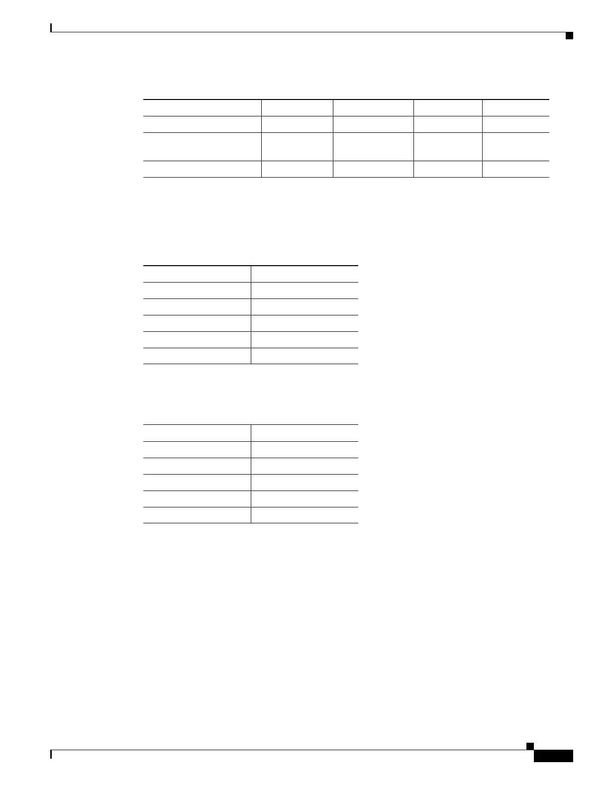
Maximum threshold 400 percent 400 percent 400 percent 400 percent
SRR shaped weights
(absolute)
1
25 0 0 0
SRR shared weights
2
25 25 25 25
1. A shaped weight of zero means that this queue is operating in shared mode.
2. One quarter of the bandwidth is allocated to each queue.
Table 32-9 Default Egress Queue Configuration (continued)
Feature Queue 1 Queue 2 Queue 3 Queue 4
Ta b l e 32-10 Default CoS Output Queue Threshold Map
CoS Value Queue ID–Threshold ID
0, 1 2–1
2, 3 3–1
4 4–1
5 1–1
6, 7 4–1
Ta b l e 32-11 Default DSCP Output Queue Threshold Map
DSCP Value Queue ID–Threshold ID
0–15 2–1
16–31 3–1
32–39 4–1
40–47 1–1
48–63 4–1

 Loading...


